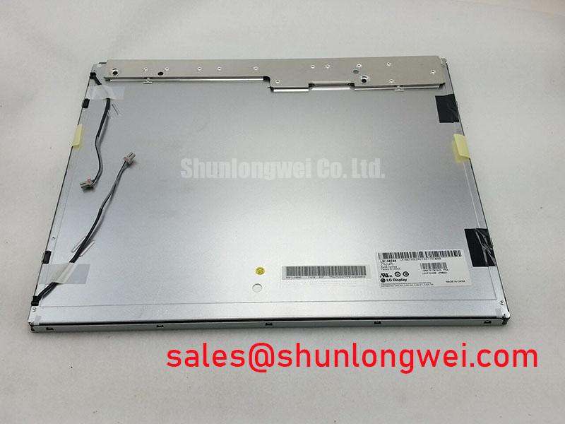
Content last revised on October 11, 2026
Full-Screen Primary Color AOI Screening: Stuck Sub-Pixels and Background Uniformity Audit
Run full-screen red, green, blue, white, black, and neutral-gray patterns before installing the LM190E08-TLJ3 in a control enclosure. I use the primary-color sequence to separate a fixed sub-pixel from a wider illumination or signal-path problem. A defect that remains at the same coordinate through each color pattern deserves pixel-level inspection, while broad luminance variation across the panel should be assessed as a uniformity or backlight issue.
A 45-degree flashlight inspection with the display showing a dark field can reveal local shadows, edge leakage, surface contamination, or changes in the optical stack that are difficult to see under normal ambient light. Move the light slowly across the viewing surface rather than aiming it directly at the panel. This method does not prove a driver-chip fracture, but a narrow line defect that changes with pressure, temperature, or viewing angle should be isolated from the panel signal path without pressing the glass or bezel.
For a replacement evaluation, capture the same test patterns on the removed display and the candidate unit at identical camera exposure and brightness settings. Record the location, width, and persistence of any abnormal area. Backlight aging is best treated as a measured luminance trend, not as a guaranteed service-life figure for this model. If a constant-current driver is used in the host equipment, check its regulation, open-load response, short-circuit response, and diagnostic output separately. A nominal PWM range such as 200 Hz to 1 kHz can be used as a system test window only when it matches the controller and camera requirements; it is not an LM190E08-TLJ3 factory rating.
Industrial display optical behavior varies with cover glass, diffuser geometry, ambient light, and enclosure design. The Winstar industrial TFT-LCD and OLED display reference is useful when comparing general display integration practices, but it should not be treated as a specification for this LG Display module.
Logic Supply Voltage Sequencing and Driver IC Latch-Up Risk Review
Before applying power, compare the replacement panel connector, cable orientation, signal assignment, and controller documentation with the original assembly. The supplied product identity confirms a TFT-LCD active matrix color display module, but the host system must verify the required logic supply, interface standard, backlight connection, and power sequence from the original panel documentation. Do not assume that a connector with the same mechanical appearance has the same electrical mapping.
During commissioning, observe the logic rail and display-enable relationship with an oscilloscope. The commonly discussed 3.3 V or 5.0 V categories should be treated as system verification points rather than interchangeable choices. A controlled power-on ramp can help prevent undefined input states, but the acceptable rise time, enable delay, reset behavior, and discharge sequence must come from the panel and controller requirements. If the system uses differential video, inspect pair symmetry, return-current continuity, termination, and connector seating. A nominal 100 ohm differential routing target is a board-level design consideration, not a confirmed rating for this display module.
JEIDA and VESA data mapping can produce similar visual symptoms when the mapping is wrong: split images, incorrect colors, unstable bands, or partial-screen content. Confirm the transmitter configuration against a known-good panel before changing timing values. If the image is stable at room temperature but becomes slow or uneven in a cold enclosure, assess liquid-crystal response, heater control, condensation risk, and the actual operating-temperature specification together. A heater strip should never be treated as an automatic accessory of this model.
For service work on AGV or forklift telematics displays, inspect the cable strain relief after vibration exposure and check that the panel is not being twisted by the enclosure. Maintenance Note: isolate power before disconnecting the display cable, and inspect the airflow path and sealing gasket during scheduled service.
Super-IPS or MVA Wide Symmetric Viewing Cone Evaluation for Multi-Angle Consoles
Evaluate viewing performance from the actual operator positions rather than relying on a single front-facing inspection. The terms Super-IPS, MVA, and a symmetric 85°/85°/85°/85° viewing cone must be confirmed by the applicable LG Display datasheet before being assigned to the LM190E08-TLJ3. They should not be inferred from the model number or from the appearance of a working sample.
For a multi-angle HMI console, display a grayscale ramp, saturated colors, and fine text while moving horizontally and vertically through the operator’s normal sight lines. Look for grayscale inversion, black-level lift, color shift, and loss of fine detail. This assessment is more useful than judging brightness alone because reflected light, cover glass, polarizer orientation, and surface treatment all influence readability.
Anti-glare or anti-reflective behavior should be checked with the intended enclosure window, overhead lighting, and sunlight direction. A matte surface can reduce mirror-like reflections while also changing perceived sharpness; a clear surface can preserve apparent contrast but reflect surrounding equipment. Confirm whether the installed assembly includes a separate protective window or touch layer before comparing optical results. Engineers evaluating the wider industrial TFT-LCD technology background can consult The Ultimate Guide to Industrial TFT LCD Technology.
At sub-zero ambient conditions, response-time changes should be measured with the final enclosure, display timing, and thermal control active. Do not convert a cold-start observation into a panel lifetime claim. For an AGV or rugged forklift display, assess image readability, condensation control, and mechanical restraint as one installation problem, while keeping the panel’s verified environmental limits as the governing boundary.
Preventing Localized Light Guide Plate Compression Warp on Dark Screen Fields
Dark-field inspection should be performed after the panel has been mounted in its intended bezel, because uneven frame loading can create optical nonuniformity that is absent on a loose bench. Display the black and dark-gray patterns, reduce surrounding reflections, and inspect the corners, edge bands, and fastener locations from several angles. A localized shadow may relate to mounting pressure, gasket displacement, cover-window contact, cable interference, or an optical assembly condition; it should not be assigned to one cause without comparison testing.
The chassis opening, bezel flatness, gasket compression, and fastener pattern must be controlled by the equipment designer. The supplied product information does not establish a factory chassis tolerance or an approved M3 torque value for this model. Values such as 0.35 to 0.45 N·m may appear in general mechanical integration discussions, but they must not be presented as an LM190E08-TLJ3 installation specification. Use the host equipment drawing and validate uniform contact with a cross-pattern tightening sequence and a before-and-after dark-field image.
Do not allow the display cable, foam, gasket corner, or bezel lip to press into the active area. Thermal cycling can change gasket seating and enclosure stress, so repeat the dark-field inspection after the assembly reaches its intended operating condition. When the panel is considered for an industrial HMI or vehicle telematics console, check vibration restraint without transferring chassis distortion into the glass or optical stack.
Interface integrity remains part of the mechanical review. TTL or LVDS clock quality, data hold behavior, connector retention, and temperature-related timing drift should be verified at the system transmitter and receiver. If the design uses a companion display or backlight assembly, the NL8048AC19-14F can be reviewed as a separate peripheral display solution, not as a substitute specification for the LM190E08-TLJ3. For same-size and same-resolution comparison work, engineers may also review LM190E08-TLG5 as a separate reference model.