Content last revised on October 20, 2026
Incoming Benchtop Inspection: COG/TAB Anisotropic Conductive Film Integrity
Begin the optical inspection with a controlled primary-color sequence rather than relying on a single full-white image. Red, green, and blue fields expose different classes of pixel and line defects, while black reveals light leakage, edge glow, and nonuniform dark-field behavior. Follow these fields with white and mid-gray screens to identify brightness variation that may be difficult to see on saturated colors.
Use a flashlight at approximately 45 degrees as a Design Consideration when investigating a dark vertical or horizontal region. A dark shadow that changes with the position of the light can point toward surface, diffuser, or backlight behavior, whereas a stable line that remains aligned with the same pixel region deserves closer examination around the display edge and bonded-driver area. This technique is an isolation aid, not a model-specific failure threshold.
Inspect the visible edge of the glass and the flexible connection area under diffuse illumination. Look for lifted edges, creasing, foreign particles, uneven pressure marks, or a cable that is not seated squarely. COG and TAB bonding zones are mechanically sensitive, so applying pressure to the glass while attempting to restore an intermittent line can create a second fault. A known-good controller and cable provide a more reliable comparison than repeated reseating alone.
Cold testing requires a different interpretation of image motion. As ambient temperature falls, liquid-crystal viscosity can increase and gray-to-gray transitions may appear slower during the first minutes after power-up. If the equipment specification includes operation around −20°C to −30°C, treat any heater strip or enclosure warming strategy as a system-level design consideration. Record the cold-start image response, warm-up time, and uniformity at the actual panel mounting position rather than assigning the observed delay to the LCD alone.
💡 Bench Tip: Use ESD protection and close the display cable latch only after the cable is fully parallel and evenly inserted, with machine power removed before any connection change.
For the physical and optical principles behind transistor-controlled liquid-crystal pixels, consult Thin-Film-Transistor Liquid-Crystal Display (TFT LCD) Technology. The article is useful for distinguishing pixel-array behavior from illumination and interface faults during incoming quality checks.
Aluminum Heat Spreader Sizing and Thermal Interface Placement along Narrow Display Edges
Place any proposed aluminum heat-spreader rail against the enclosure heat path, not directly against an active viewing area or flexible bonded section. The objective is to reduce localized temperature concentration around narrow edges while preserving the mechanical flatness of the display assembly. Rail length, thickness, contact pressure, insulation, and enclosure airflow remain system-dependent choices and are not confirmed specifications of the STK6714AMK4.
During evaluation, map the front surface and rear frame after the panel has operated through the intended brightness range. A localized warm region may originate from the backlight driver, an enclosure contact point, a poor thermal interface, or restricted airflow. Do not use a heat spreader to compensate for a distorted bezel or an incorrectly compressed display stack. A flat mounting plane and consistent contact condition should be established before comparing thermal images.
LED brightness control also requires an interface check. If the host system uses PWM dimming, evaluate the selected frequency and duty-cycle response across the complete brightness range. A project may investigate a 200 Hz to 1 kHz PWM window as an engineering starting range, but the suitable value depends on the display electronics, camera exposure, audible noise requirements, and machine-control environment. Confirm that the panel actually accepts the host dimming method before applying a PWM signal.
The requested panel data identifies the unit as a TFT-LCD active matrix color display module but does not confirm an LED backlight lifetime rating, L70 or B50 value, optical bonding construction, or optical diffuser material. For that reason, long-term backlight claims should be based on the applicable panel documentation and the completed system thermal test. In an HMI that displays fixed menus for long periods, rotate maintenance screens or introduce controlled visual variation where the host application permits it. This is a display-management recommendation rather than a guaranteed burn-in prevention specification.
| Qualification item | STK6714AMK4 record | Integration action |
|---|---|---|
| Manufacturer | AUO | Match the replacement label and equipment documentation |
| Display category | Industrial Grade LCD/HMI Panel | Confirm the original machine display interface |
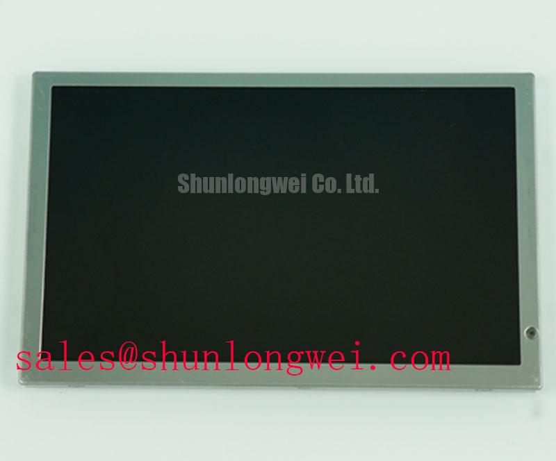
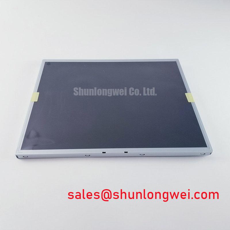
| Display construction | TFT-LCD Active Matrix Color Display Module | Check controller, cable, and optical stack compatibility |
| Form factor status | Decoded Baseline / Standard Form Factor | Verify outline, fixing points, and bezel clearance before fitting |
| Voltage, current, resolution, and pinout | Consult Datasheet | Do not energize from assumed values |
Mitigating Gray-to-Gray Response Time Escalation during Cold-Start Machine Power-Up
Cold-start image assessment should capture both the first usable frame and the transition behavior after the enclosure reaches its operating condition. Use moving gray blocks, text scrolling, and a mid-gray transition rather than judging only a static splash screen. Slower gray-to-gray behavior can be more visible on machine-tool graphics with fine diagonal lines, alarm banners, or rapidly changing process values.
Power sequencing deserves attention when the display is connected to a controller that initializes faster than the panel electronics. The integrator should verify the original panel documentation for supply voltage, enable behavior, reset timing, and signal order. A white screen, residual image, or delayed picture can involve the host processor, display power rail, backlight enable path, cable seating, or signal initialization. Capture the supply and control signals during startup with the approved test method instead of changing the sequence by guesswork.
At shutdown, remove the display enable and data activity in the sequence required by the host design. This can reduce the chance of a visible residual frame, but the correct order is system-specific. A discharge path, controller reset state, or backlight control circuit may affect the result. The panel page identifies no confirmed power-sequencing limits for this model.
For outdoor-facing or brightly lit factory areas, evaluate contrast under the actual enclosure window and ambient illumination. A project requirement such as contrast above 500:1 at 50,000 lux must be verified by the system owner using the completed optical stack; it should not be presented as a confirmed STK6714AMK4 rating. Anti-glare treatment, cover-lens reflections, viewing direction, and ambient light angle can change perceived contrast even when the LCD electronics are operating correctly.
Wide-angle viewing assessment should use the machine’s real operator positions. Check black level, gray neutrality, and color shift from above, below, and both sides of the intended viewing cone. IPS or MVA terminology should not be assigned to this model unless the applicable AUO documentation confirms the panel technology. The same caution applies to optical bonding, moisture sealing, and anti-glare coatings: these are integration attributes unless explicitly listed for the supplied panel configuration.
Chassis M3 Fastener Torque Sizing to Reduce Optical Mura Risk
Mechanical inspection begins with the bezel opening, mounting lands, cable bend path, and rear clearance. A display can show mura, edge shadowing, or brightness variation when the chassis applies uneven pressure, even when the panel passes the electrical image test. Mounting holes and brackets should be aligned before tightening so the display is not pulled into position by the fasteners.
A cross-pattern tightening method is a useful Design Consideration for distributing frame pressure. The proposed 0.35 to 0.45 N·m range is a general engineering reference for evaluating an M3 chassis assembly, not an official STK6714AMK4 mounting specification. The final torque must follow the equipment manufacturer’s mechanical drawing, fastener material, bracket stiffness, gasket condition, and measured optical result. Check the panel again on white, gray, and black fields after the chassis has reached its final clamped condition.
For high-EMI factory environments, differential display links should be routed as a controlled pair with a continuous reference path and minimum unnecessary stub length. A project may use 100 Ω ± 10% differential impedance and a skew target of 50 ps or less as a board-level engineering requirement when supported by the chosen interface standard. These values are not confirmed electrical specifications for the product listing. Validate them against the actual controller, connector, cable, and signal protocol.
Keep power and backlight switching paths away from sensitive display data routing, and verify the image while motors, contactors, and variable-frequency drives operate in their normal switching states. If intermittent lines appear only during machine motion, compare the display signal at the controller and panel ends, inspect cable retention, and check the chassis reference path. The Ultimate Guide to Industrial TFT LCD Technology provides a broader technical reference for display selection, signal integrity, and common integration misconceptions.
Before approving the STK6714AMK4 for a repair, match the original outline, connector orientation, controller timing, backlight control method, and mounting interface. This AUO TFT-LCD active matrix color module is suitable for evaluation in industrial HMI and machine-tool operator-terminal service work when those interface and mechanical conditions agree with the existing equipment.