
Content last revised on September 26, 2026
PM100RRS060 Field Diagnostics and Commissioning: Voltage Margin and Site Conditions
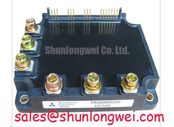
Isolate the DC link, confirm it is discharged, and check the marked power and control terminals against the equipment schematic before taking cold readings on a PM100RRS060. The identified product is a Mitsubishi Electric intelligent power module rated at 600 V and 100 A in a Mitsubishi IPM Module package. These are Official Specifications; they do not, by themselves, establish terminal functions, mounting dimensions, isolation test conditions, or compatibility with a particular inverter.
Start the incoming check with the full part marking and the machine’s original wiring record. Photograph the terminal arrangement before disconnecting conductors, then compare each planned meter probe position with the documented circuit. On a disconnected module, a multimeter’s diode mode can help record cold, polarity-dependent readings between documented power terminals. Treat those readings as a comparison record, not a pass threshold: the measurement path depends on the module’s confirmed internal circuit and on anything still connected externally.
Bench Tip: Protect the control terminals from electrostatic discharge and compare cold readings only with a documented reference measured under the same conditions.
For a commercial string inverter or microgrid energy-storage repair, designers should compare the equipment’s measured DC-link behavior, including switching transients, with the 600 V module rating. A steady bus reading alone cannot establish switching margin. If a site operates at altitude, radiation-related single-event effects and any required voltage derating belong in the equipment-level reliability assessment. Without a product-specific qualification source and site conditions, a failures-in-time rate or single-event burnout prediction for this module would be unsupported.
Inspect terminal spacing, insulation barriers, cable routing, and contamination in the actual assembly rather than assigning a generic clearance rule to the module. Any insulation withstand test should follow the original equipment and module documentation; the 600 V rating is not an insulation test voltage. Mitsubishi Electric’s power semiconductor information provides broader device context, but the applicable product documentation remains necessary for test limits.
PM100RRS060 Field Diagnostics and Commissioning: Baseplate Thermal Interface Control
Before mounting, inspect the heatsink contact area and the module’s mating surface for damage, debris, and old interface material. Apply the thermal interface material specified for the assembly in a consistent layer, then mount the module using the documented fastener sequence and torque. Excess material can interfere with contact, while gaps can increase thermal resistance. Neither a grease thickness nor a screw torque should be treated as a PM100RRS060 factory requirement without its mounting instructions.
If the removed unit shows an uneven contact pattern, check heatsink flatness, fastener condition, and the equipment’s mounting procedure before assigning the cause to the module. Record the contact pattern during disassembly and compare operating temperatures at equivalent load conditions after reassembly. This is a Design Consideration: temperature differences can prompt further inspection, but they cannot independently identify a failed semiconductor or prove a thermal interface fault.
Switching-waveform checks require the same restraint. A recovery-related transient, if present in the documented circuit, may be influenced by the switching path, layout, and external suppression network. Compare voltage and current waveforms with a known-good operating record and assess any snubber changes at system level. A module rating does not establish radiated-emissions compliance for the finished inverter.
PM100RRS060 Circuit Protection and Reliability: Checking Control Returns and PCB Symmetry
Trace the control connector to the driver board before interpreting a switching fault. Confirm supply polarity, enable and fault wiring, and the return path against the equipment schematic. Do not assume that a terminal is a separate Kelvin emitter or that this IPM exposes the same gate connections as a discrete IGBT module; those functions need confirmation from the exact terminal documentation.
Where the documented interface provides separate sensing or control returns, keep their routing distinct from high-current paths as a Design Consideration to limit noise coupling. If unexpected switching or a fault indication appears during commissioning, capture the control supply and relevant terminal waveforms with suitable isolated instrumentation. Compare them at matching operating conditions before changing driver components. The equipment designer should determine timing and protection settings from the confirmed module interface and switching tests.
In repair-material evaluation, CM100DY-12E is a separate device to assess against the original schematic, package, control method, and protection requirements, not a confirmed drop-in replacement for PM100RRS060. Likewise, CM300DXDX1-24A can be examined as a distinct component in a wider power-conversion topology; its role must be established from that system’s drawings. For general switching-path and driver-layout considerations, see Precision Gate Drive Design. Mitsubishi Electric’s semiconductor device information is another reference for separating device characteristics from equipment-level design decisions.
PM100RRS060 Operational Boundaries: Evaluating DC-Link Layout and Low-Inductance Connections
Check the DC-link capacitor bank, bus connections, and module terminals as one current path. Loose joints, damaged insulation, or an altered conductor route warrant correction under the equipment service procedure before an energized test. As a Design Consideration, a compact, balanced current loop helps limit inductive overshoot during switching; the acceptable geometry must be established by the system designer, not inferred from the 100 A rating.
During a controlled switching test, capture the peak voltage at the appropriate documented measurement points and compare it with the 600 V device rating under the equipment’s relevant operating conditions. Bus voltage and switching-induced overshoot both contribute to the observed peak. If the margin is insufficient, investigate connection integrity, current-loop geometry, switching behavior, and the existing suppression network before selecting changes. Snubber capacitance and any target for stray inductance are system-specific outcomes of those measurements, not published specifications here.
For a string-inverter or storage-converter service decision, finish by matching the original part marking, terminal map, mechanical fit, control interface, and measured operating boundary to the equipment documentation. An unresolved mismatch in any of those checks remains an integration question even when the replacement candidate carries the same nominal voltage and current ratings.



