


Content last revised on September 30, 2026
PM100RSE060 Braking Circuit Checks and Thermal Loading
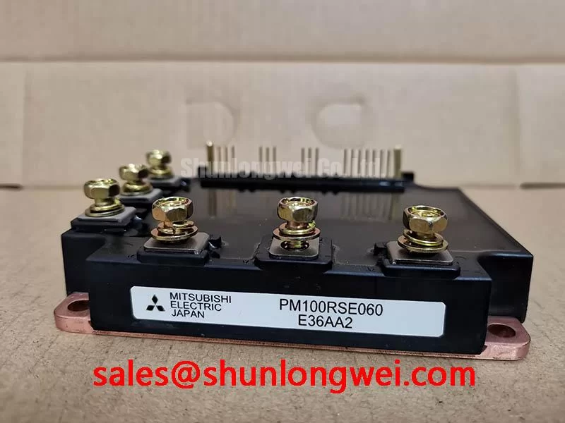
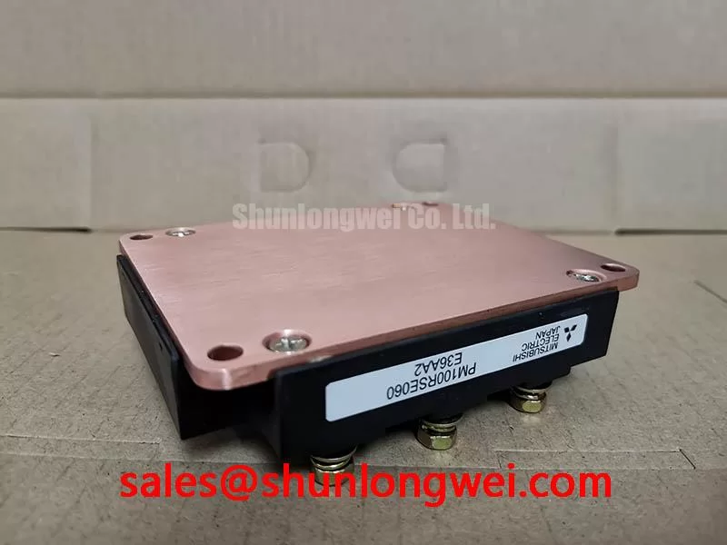
PM100RSE060 is a Mitsubishi Electric intelligent power module in a Mitsubishi IPM Module package. Its rated voltage is 600 V and its rated current is 100 A (Official Specifications).
Measure the discharged DC link and inspect the braking resistor circuit when a drive trips during motor deceleration. A rising DC link during a stop can point toward inadequate braking action, but it does not identify the failed part by itself. Check the drive fault record, resistor continuity, wiring and commanded braking behavior before attributing the trip to the PM100RSE060.
For a heavy-duty variable frequency AC motor drive, the engineer should establish from the drive schematic whether braking uses a separate chopper, another module or a circuit associated with the power assembly. The 600 V voltage rating and 100 A current rating are Official Specifications for PM100RSE060; they are not braking-resistor ratings or proof that this module contains a braking switch. Match terminal functions to the equipment drawing before probing or reconnecting the power stage.
Braking resistor selection is a system Design Consideration. The stop profile, rotating inertia, repetition rate and cooling arrangement determine the energy the resistor must absorb. Its resistance must also suit the drive’s braking circuit: too little resistance can demand excessive chopper current, while too much can limit braking action. Compare the installed resistor and its thermal protection with the drive manufacturer’s requirements, then verify DC-link behavior during a controlled stop. The module rating alone cannot establish a safe resistor value.
On a cold assembly, look for heat discoloration at resistor terminations, loose connections and damaged insulation along the braking path. Compare suspect connections with an undisturbed section of the same equipment rather than treating a single resistance reading as a diagnosis. Keep hot resistor wiring clear of signal harnesses and maintain the clearances specified for the complete drive. ⚠️ Field Alert: Discharge and verify the DC link before disconnecting braking wiring or removing the module.
When assessing a replacement, compare the original module’s mechanical outline, terminal map, control connections and protection behavior, not just its headline ratings. PM150CSE060 may enter a substitution review, but a different model designation does not establish direct interchangeability. If the equipment has a separate upstream or auxiliary power stage, trace that stage independently; the discussion of PMH150CS1D060 provides a related selection context, not a terminal-for-terminal match to PM100RSE060.
PM100RSE060 Assembly Integrity and Isolation Layout
Check the module mounting surface, terminal tightness and control-harness routing when intermittent trips appear after a power-stage repair. A shifted connector, uneven heatsink contact or disturbed control lead can change behavior without an obvious fault in a cold diode check. Record the original wiring positions against the drive schematic, and inspect the heatsink for burrs or contamination before installing another module.
Electrical isolation is a property to verify across the complete assembly. Do not assign a reinforced-insulation voltage or a common-mode transient immunity rating to PM100RSE060 from its 600 V power rating: those are different specifications. As a Design Consideration, retain the drive maker’s specified creepage, clearance, insulating hardware and test procedure wherever power terminals, the heatsink and control circuitry meet. An isolation test applied through an assembled drive can also reach components not intended for that test, so follow the equipment service procedure.
At the control interface, use the circuit drawing to identify the supply, command and fault paths before measuring them. Scope a suspect command at the driver side of any isolator and compare it with the corresponding signal at the module interface, using measurement equipment rated and connected for that location. A pulse present on one side but absent or distorted on the other narrows the investigation; it does not, on its own, prove that an optocoupler, digital isolator or module has failed.
Fast switching can couple common-mode disturbance into control wiring. Isolator CMTI, driver sourcing and sinking capability, and gate damping are therefore system Design Considerations, not additional published ratings for this module. Keep control wiring separated from high-current switching paths where the equipment layout permits. If a repair changes a driver or external gate component, restore the documented circuit first and evaluate command fidelity and switching waveforms under controlled conditions. An arbitrary gate-resistor change can reduce visible ringing while changing switching loss or protection response.
Apply thermal interface material and mounting force according to the module and heatsink assembly instructions. Check that the module seats evenly; excess compound, trapped debris and uneven tightening can impair contact. A cold resistance comparison between accessible power terminals can help screen for a gross short, but it cannot establish insulation integrity or confirm normal operation under load.
Long Motor Leads and PM100RSE060 Output Transients
Capture the waveform at the motor terminals when trips or insulation-related complaints occur after a motor-cable change. A long cable can behave as a transmission line during a fast inverter edge; reflections may raise the motor-terminal peak above the waveform measured at the drive output. That possibility is a system Design Consideration, not a specified voltage-spike characteristic of PM100RSE060.
Use a suitable high-voltage differential measurement method and compare the drive-end and motor-end waveforms under the same operating condition. Note cable length and construction, grounding, switching settings and any existing output reactor or filter. These observations help distinguish a cable-related reflection from DC-link overshoot or a measurement artifact. Do not infer the peak at the motor from a probe placed only at the module terminals.
An output reactor or dv/dt filter is selected against the drive manufacturer’s limits, the motor insulation system, cable characteristics and thermal duty. Designers should verify its effect at the motor as well as at the drive: a filter that reduces edge stress still has to carry the operating current without introducing an unacceptable temperature rise or control interaction. The 100 A module rating is an Official Specification, but it is not a standalone filter-current selection rule.
Inspect cable shields, protective-earth connections and output terminal condition while checking the waveform. A loose connection can introduce local heating and irregular switching behavior; an altered cable route can change coupling into nearby control circuits. Treat radiated noise as an equipment-level investigation rather than claiming EMC compliance or noncompliance for an individual IPM. For broader power-stage fault patterns and application context, see Industrial Applications.
Freewheeling behavior also matters when interpreting a switching trace. Diode reverse recovery can contribute to current transients and noise, but no recovery-softness factor is established here for PM100RSE060. Compare measured behavior with the approved drive configuration rather than assigning a numerical diode characteristic from a generic power-module discussion. Mitsubishi Electric’s SiC Power Modules and SBDs material describes other power-device technologies; it should not be used to identify the internal devices of this IPM.
DC Bus Layout, Snubbers and PM100RSE060 Turn-Off Overshoot
Probe the DC-link voltage and switching-terminal peak during a controlled turn-off test when overvoltage trips follow a busbar or capacitor repair. Record where each probe is connected: a measurement at the capacitor terminals can miss a transient at the module. Compare the result with the installed assembly’s documented test condition and the 600 V PM100RSE060 voltage rating (Official Specification).
Bus-loop inductance adds to the voltage seen during rapid current change. As an Engineering Calculation, the inductive contribution follows loop inductance multiplied by the rate of current change; the measured peak also depends on the actual circuit and waveform. Reduce loop area where the equipment design permits, keep opposing current paths close and inspect bus joints for altered spacing or poor contact. No universal busbar-inductance target can be assigned to this module from its voltage and current ratings.
A snubber belongs to the complete switching circuit. Its capacitance, voltage capability, loss and physical placement should be evaluated against measured turn-off peaks, operating temperature and the drive’s approved design. Replacing only a capacitor with one that has the same nominal capacitance does not confirm equivalent pulse behavior or layout. Check its terminals and connection path before changing values, then verify the peak again at the module under the relevant load condition.
If the drive uses a bootstrap supply or an isolated gate-drive supply, inspect its waveform during the troublesome operating sequence. Supply droop, diode behavior and charging opportunities can affect the command delivered during repeated switching, but the required margin is set by that driver circuit and its timing. Compare the observed supply and fault signals with the equipment documentation instead of assigning a bootstrap-capacitor value from the PM100RSE060 power rating.
Finish the repair check with the busbar secured, control harness restored and cooling path unobstructed. Compare cold terminal readings with the service reference, confirm fault reporting at low-energy test conditions and review switching peaks as load is increased under the equipment procedure. Where altitude or radiation exposure is part of a project requirement, obtain the applicable manufacturer and system reliability evidence; neither a service waveform nor the two headline ratings supports a numerical lifetime or failure-rate claim.