

Content last revised on October 8, 2026
Field Diagnostics & Commissioning: Fault-Clearing Dynamics in PSS05S92F6-AG Topologies
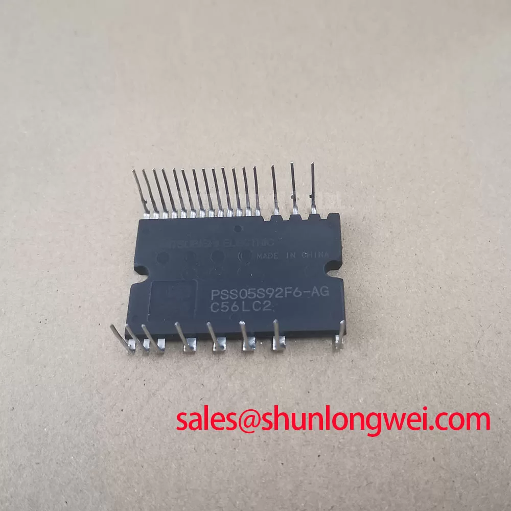
With the equipment isolated and its DC link verified discharged, compare the cold terminal readings of the PSS05S92F6-AG with the documented pinout before connecting a gate driver. The confirmed product ratings are 600 V and 5 A, and its package classification is Power Module (Official Specification). Those values establish an initial identity check, not a complete basis for approving a repair: terminal functions, protection behavior, thermal limits and mounting requirements still need confirmation against the applicable StarPower documentation.
Start an incoming inspection with the module disconnected from the power stage. Identify each terminal from the approved pin diagram, record cold resistance readings, and use the multimeter diode function only across paths identified by that diagram. A repeatable forward reading in one direction and a different reading with the probes reversed can help establish a bench baseline; it does not, by itself, establish switching health or a model-specific pass threshold. Compare readings with a documented known-good unit under the same meter conditions where one is available. The exact forward-voltage acceptance limits are not established by the confirmed ratings above.
💡 Bench Tip: Keep the gate terminals under appropriate ESD protection during cold measurements, and do not treat an undischarged DC link as isolated equipment.
For a reported short-circuit trip, separate the module check from the driver and controller checks. Trace the fault input on the equipment schematic, then examine the driver supply, sensing path, blanking behavior and fault latch with suitable isolated instruments. Type-I and type-II short circuits describe different system fault conditions; neither label establishes that the PSS05S92F6-AG contains desaturation detection or a particular soft turn-off sequence. As a Design Consideration, a driver that detects a fault and controls turn-off can help limit stress, but its threshold and response must be validated against documented device limits and the measured power-stage waveform. A fixed detection-time claim cannot be inferred from the 600 V and 5 A ratings.
During commissioning, observe the switching-node voltage and gate signal at the fault transition rather than interpreting a controller fault code as proof of a failed module. Keep the commutation path compact to reduce inductive overshoot, then verify the measured peak against the device voltage rating under the equipment’s actual DC-link conditions. Check terminal spacing and the assembled insulation arrangement against the equipment’s insulation design; package classification alone supplies no creepage, clearance or withstand-voltage figure. If the drive board uses an optocoupler or digital isolator, evaluate its common-mode transient behavior in the assembled circuit rather than assigning the isolator’s capability to the power module.
A semiconductor fuse is another system-level protection element, not a substitute for switching-fault control. When a hard short is suspected, compare the selected fuse’s documented clearing behavior and let-through energy with the complete power-stage protection design. Likewise, phase-controlled rectifier conduction angle and its associated line harmonics belong to the upstream supply assessment. Neither characteristic can be established by a static test of this module.
PSS05S92F6-AG Thermal-Electrical Optimization: Symmetrical Busbar Geometry and Current Sharing
Before fitting the PSS05S92F6-AG to a heatsink, inspect the mounting faces and compare the proposed hardware with the equipment drawing. The confirmed Power Module classification does not specify a mounting torque, interface thickness or thermal resistance. As a Design Consideration, even contact and a suitable thermal interface help the assembled cooling path perform consistently; the final materials, fastener settings and temperature acceptance criteria must come from the mechanical design and applicable device documentation.
Do not assume that this model has a positive on-state-voltage temperature coefficient over the operating range simply because current sharing is a familiar IGBT design topic. That behavior requires device-characteristic data at the relevant current and temperature. If the equipment parallels modules, the engineer should compare documented on-state characteristics and measured branch currents after thermal stabilization. Static sharing and switching sharing are separate questions: matched physical paths and symmetrical busbar geometry can reduce branch differences, while comparable driver paths and gate-loop routing matter during transitions. Validate both conditions at the assembled power stage rather than using equal cold resistance as proof of equal operating current.
Place voltage probes at corresponding electrical points when comparing parallel branches. Unequal readings may reflect probe placement, connection resistance, thermal contact or driver timing as well as a device difference. Record heatsink and accessible case temperatures alongside load conditions so that a repeat test is meaningful. For background on cooling-path choices, The Advanced Thermal Management Revolution discusses broader thermal-management approaches; it does not establish which internal construction or cooling method applies to this module.
Industrial inverter welders and medium-frequency induction-heating supplies are potential compatibility assessments, not stated intended applications. Their switching arrangement, current waveform, cooling system and mounting footprint must all be checked before treating a shared voltage rating as meaningful fit. The H2G150ND06M1 can be placed on a comparison worksheet, but no substitution follows from its listing: compare the manufacturer pinouts, topology, electrical limits and mechanical interfaces independently.
PSS05S92F6-AG Circuit Protection & Reliability: DC-Bus Margin and Insulation Checks
For the 600 V rated module (Official Specification), first establish the highest DC-link voltage the equipment can present and then capture turn-off peaks at the device terminals. As a Design Consideration, preserve voltage headroom for transients; the required headroom is determined by measured switching behavior and the documented device limits, not by an assumed universal derating percentage. Inspect the DC-link capacitors, local connections and busbar joints if peak voltage changes after service work. A steady bus reading alone cannot reveal the peak imposed during turn-off.
Cosmic-ray-related single-event burnout and altitude-dependent reliability are specialized qualification questions. The available confirmed specifications do not provide this model’s FIT rate, neutron-response data or altitude derating curve, so none can be calculated responsibly for this product page. For equipment deployed at altitude, request the applicable manufacturer reliability guidance and assess operating voltage, environment and mission requirements at system level. Avoid treating a generic altitude threshold as a device-specific failure boundary.
Insulation assessment also needs a defined test basis. Inspect terminal separation, contamination, mounting condition and the equipment’s intended protective barriers, then check creepage and clearance against its documented working voltage and installation environment. Do not apply an arbitrary hipot setting to an unidentified terminal pair. A dielectric test should follow the approved assembly procedure and the manufacturer’s stated insulation data where available; no insulation-withstand value is established by the confirmed product information here.
If the system includes regenerative braking, examine the braking chopper and resistor as part of a rising-DC-link investigation. Their energy absorption is a system function, not an attribute of the module’s 5 A rating. Similarly, control strategies can affect the current demands placed on an inverter without changing this module’s factory limits. Deadbeat control provides context for fast current-tracking control; droop speed control describes a different control context and should not be used as evidence of parallel-inverter capability or a PSS05S92F6-AG rating.
Transient Dynamics & Electrical Design: Common-Mode Current at the PSS05S92F6-AG Interface
When this module is evaluated for a motor-drive power stage, capture the switching waveform at both the power-stage output and the motor terminals if lead length is significant. Reflections on a long cable can make motor-terminal peaks differ substantially from the voltage observed at the inverter. Do not assume a particular spike multiplier from the cable length alone: the measured result depends on the source, cable, termination and switching waveform. Compare the captured terminal peak with the motor-insulation design limits and examine an output filter only in the context of those measurements.
High-frequency common-mode current can return through cable shielding, chassis and a motor’s parasitic paths. Bearing-current risk is therefore assessed at the assembled drive, not assigned as a standalone property of the PSS05S92F6-AG. As a Design Consideration, review grounding and cable termination, measure the relevant common-mode waveform, and evaluate a choke or output filter when those measurements and the motor documentation support one. Filter selection must account for load current, switching conditions and thermal performance; the module’s 5 A rating alone does not size it.
If a post-repair drive shows unexpected trips only after the output cable is attached, compare waveforms with the documented healthy configuration before changing the module. Check the output connection, cable route, sensing leads and driver isolation path for differences introduced during the repair. A trip coinciding with a switching edge may indicate a transient coupling or sensing issue, but it is not a single-cause diagnosis. Resolve the observed waveform and fault timing against the equipment schematic, then repeat the test within the approved commissioning procedure.