


Content last revised on June 2, 2026
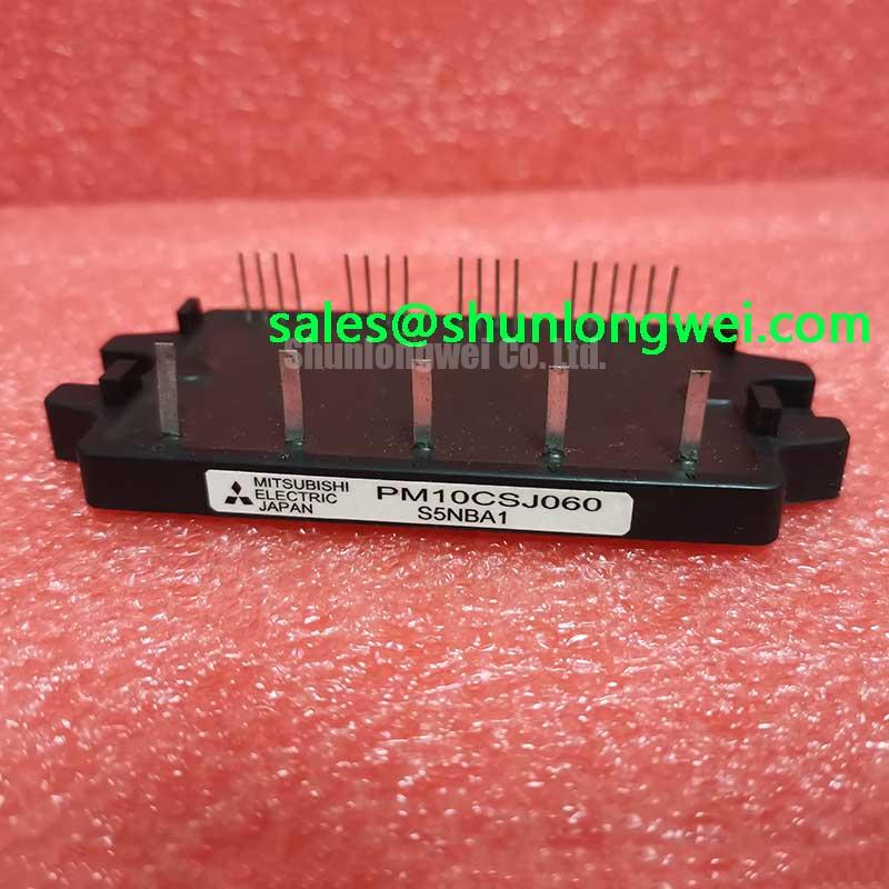
PM10CSJ060 Mitsubishi IPM: An In-Depth Technical Review for 600V/10A Integrated Motor Drives
Accelerating Compact and Reliable Low-Power Inverter Design
The Mitsubishi PM10CSJ060 is an Intellimod™ Intelligent Power Module (IPM) engineered to streamline the development of high-performance, low-power three-phase motor drives. This module provides a fully integrated inverter solution by consolidating the power stage and critical control logic into a single compact package. With core specifications of 600V | 10A | Integrated Gate Drive & Protection, it delivers key engineering benefits including a drastically simplified design cycle and fundamentally enhanced system reliability. It directly addresses the challenge of building robust motor control systems by integrating the gate drivers, protection circuits, and power switches, eliminating common sources of design error and external component failure. For low-power motor applications up to ~1.5kW where board space and time-to-market are critical constraints, the PM10CSJ060 offers a compelling, highly integrated solution.
Key Parameter Overview
Analyzing the Specifications for Integrated System Design
The technical specifications of the PM10CSJ060 reflect its nature as a complete, self-contained inverter power stage. The parameters are organized to highlight the performance of the power devices alongside the characteristics of the embedded control and protection functions, providing a holistic view for system architects.
| Parameter Category | Specification | Value | Test Conditions |
|---|---|---|---|
| Absolute Maximum Ratings (Tj=25°C unless otherwise noted) | Collector-Emitter Voltage (VCES) | 600 V | |
| Collector Current (IC) | 10 A | Tc = 25°C | |
| Collector Power Dissipation (PC) | 35.7 W | Per IGBT | |
| Inverter Electrical Characteristics | Collector-Emitter Saturation Voltage (VCE(sat)) | Typ. 1.9 V / Max. 2.5 V | IC = 10 A, VD = 15V |
| Short Circuit Withstand Time (tsc) | > 10 µs | VCC = 400V, Tj = 125°C | |
| Switching Times (ton / toff) | Typ. 1.0 / 1.5 µs | Inductive Load | |
| Control & Protection Characteristics | Control Supply Voltage (VD) | 15 V (13.5V - 16.5V) | |
| Control Input Threshold Voltage (Vth(on) / Vth(off)) | 0.8 V / 2.5 V | TTL Compatible, 3.3V/5V Class | |
| Fault Output (FO) | Open Collector Output | Signals SC, OT, UV Protection |
Download the PM10CSJ060 datasheet for detailed specifications and performance curves.
Application Scenarios & Value
System-Level Benefits in Compact Motor Control
The primary value of the PM10CSJ060 lies in its ability to accelerate the development of compact and reliable motor control systems. Consider the engineering challenge of designing a Variable Frequency Drive (VFD) for a high-efficiency commercial HVAC fan or a residential appliance pump. In these applications, the physical footprint of the control board is often severely restricted, and long-term reliability is paramount.
A traditional design using discrete IGBTs requires a significant number of external components: six gate drivers, optocouplers for isolation, complex circuitry for short-circuit and over-temperature detection, and a robust power supply for the drive logic. This not only increases the PCB area but also introduces numerous potential points of failure and complicates assembly. The PM10CSJ060 directly solves this by integrating all these functions into one module. What is the primary benefit of its integrated nature? A significant reduction in design complexity and PCB footprint. The module's low VCE(sat) of 1.9V (typ) minimizes conduction losses, which simplifies thermal management and allows for a smaller heatsink—further contributing to a compact final product. Engineers can focus on implementing advanced motor control algorithms using Pulse Width Modulation (PWM) rather than on the intricacies of gate drive and protection design. For applications requiring higher current output within the same functional family, the PM20CSJ060 provides a 20A capability.
Technical Deep Dive: Integrated Protection and Control
A System-Level View of the On-Chip Safety and Interface Logic
The "Intelligent" aspect of the PM10CSJ060 is its comprehensive suite of built-in protection and control interface features, which form a crucial layer of defense for the power stage. These circuits are precisely matched to the characteristics of the internal IGBTs, offering a level of coordinated protection that is difficult to achieve with discrete components. The on-chip protection circuits function like an automotive airbag system for the power stage. Instead of relying on a separate, slower external controller to detect a critical fault, the IPM deploys its protection instantly and autonomously, preventing catastrophic damage to the core components.
The key protections include:
- Short-Circuit (SC) Protection: Each of the six IGBTs is monitored for desaturation. If a short-circuit event occurs, the integrated logic detects the rapid rise in collector-emitter voltage and initiates an immediate, controlled shutdown of the corresponding IGBT to prevent destructive failure.
- Over-Temperature (OT) Protection: An internal temperature sensor is placed near the IGBT chips. If the substrate temperature exceeds a safe threshold, the module sends a fault signal and shuts down the inverter to prevent thermal runaway.
- Control Supply Under-Voltage (UV) Lockout: This circuit monitors the gate drive supply voltage (VD). If the voltage drops below the level required for proper IGBT gate control, the module shuts down to prevent insufficient gate drive, which could lead to high conduction losses and potential device damage.
When any of these protection functions are triggered, the module pulls the open-collector Fault Output (FO) pin low. This provides an unambiguous signal to the host microcontroller, enabling it to initiate a safe system shutdown and log the error for diagnostic purposes, creating a truly robust and self-protecting power system.
Frequently Asked Questions (FAQ)
How does the integrated fault output (Fo) signal on the PM10CSJ060 contribute to overall system safety?
The Fault Output (Fo) acts as a critical communication link between the power stage and the system's master controller. By providing a single, clear "fault" signal for short-circuit, over-temperature, or under-voltage events, it enables the microcontroller to immediately halt PWM signals and safely stop the motor. This prevents cascading failures and allows the system to enter a safe state, improving both equipment and operator safety. It transforms the module from a simple switch into a self-aware component of the system's safety architecture.
What is the key advantage of the PM10CSJ060's TTL-compatible control inputs for system design?
The direct TTL (3.3V/5V class) compatible inputs are a significant advantage for design simplification. How does the PM10CSJ060 interface with a controller? It uses TTL-compatible inputs for direct connection to a CPU or MCU. This eliminates the need for external level-shifting circuitry, buffers, or opto-isolators between the microcontroller's low-voltage logic outputs and the module's high-voltage control inputs. This reduces component count, saves valuable PCB space, and removes a potential source of signal integrity issues, leading to a more streamlined and cost-effective design process.
Engineering Assessment and Design Guidance
The Mitsubishi PM10CSJ060 is a strategic component for engineers tasked with developing low-power motor drives under tight space, cost, and time constraints. Its high level of integration provides a robust foundation, allowing design teams to bypass the complexities of discrete gate drive and protection design. For a comprehensive evaluation of its suitability for a specific application, a detailed review of the device's thermal performance curves and safe operating area (SOA) characteristics in the official datasheet is strongly recommended. This data is essential for proper heatsink selection and for ensuring long-term operational reliability under the target system's load profiles.