Content last revised on September 21, 2026
Preventing Spurious Faults: Galvanic Gate Drive Isolation, Reinforced Guidelines for PM150RLA060
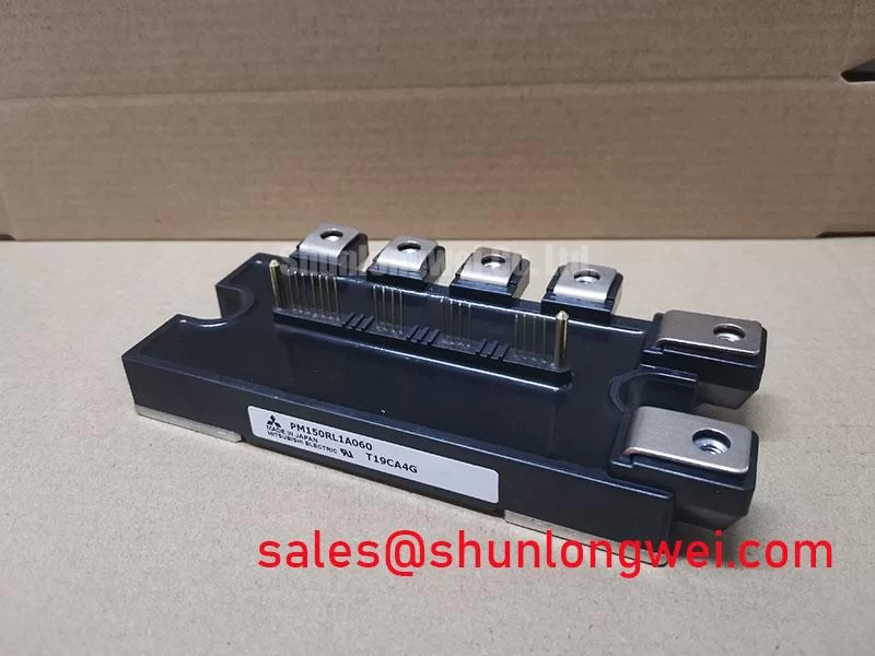
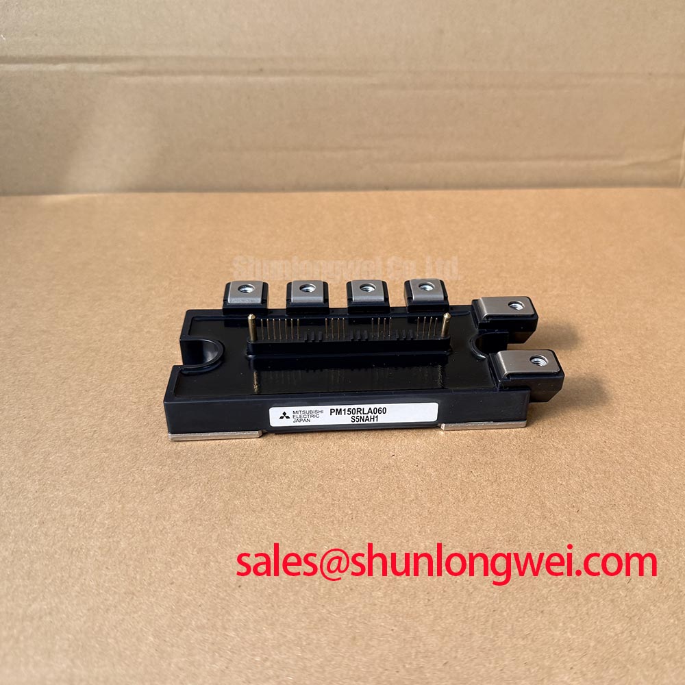
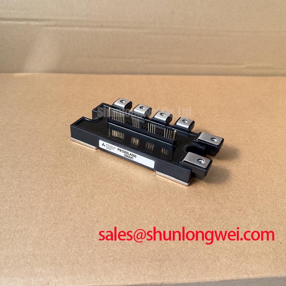
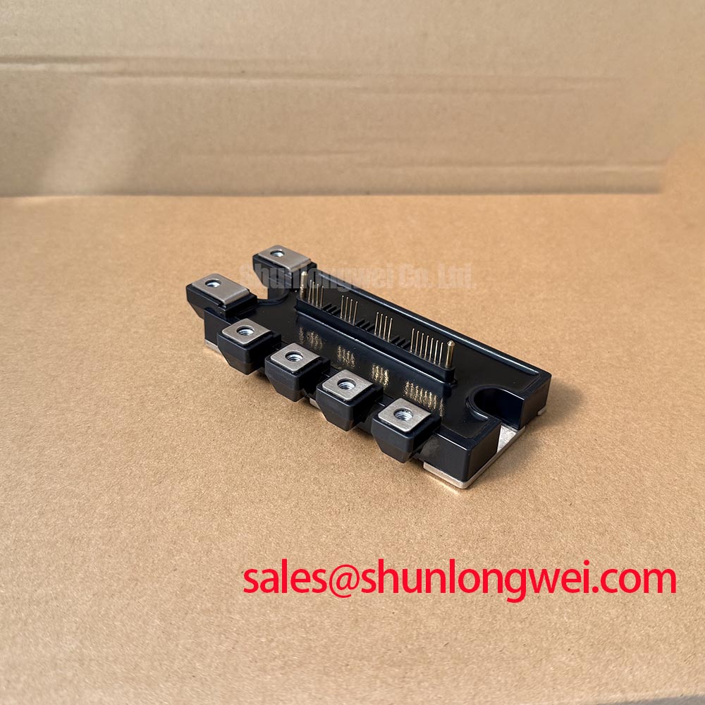
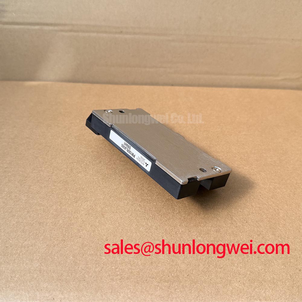
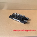
Before connecting a replacement module, isolate the drive from its DC link, discharge the stored energy according to the machine procedure, and compare the installed unit’s nameplate with the required PM150RLA060 identification, 600.0 V voltage rating, and 150.0 A current rating. This Mitsubishi Electric IPM Module should be evaluated as part of the complete inverter assembly, including the gate drive board, DC bus, current sensing path, cooling system, motor cable, and fault interlock circuit.
The stated device identity is a Mitsubishi Electric IPM Module rated at 600.0 V and 150.0 A as an Official Specification. These values define the module’s published electrical boundary, but they do not independently define safe operating conditions for a particular variable frequency drive. The actual DC bus voltage, switching waveform, motor regeneration level, cooling capacity, gate drive arrangement, and protection response remain system determined.
| Official product attribute | Specified value |
|---|---|
| Manufacturer | Mitsubishi Electric |
| Product model | PM150RLA060 |
| Rated voltage | 600.0 V |
| Rated current | 150.0 A |
| Package category | Mitsubishi IPM Module |
Unexpected inverter trips, unstable speed control, or gate related alarms should be investigated at the interface between the controller and the power stage rather than attributed to one cause. Inspect the drive board for contamination, moisture traces, damaged connectors, loose reference connections, and deterioration around isolation components. A contaminated control board or an unintended return path can alter the gate reference during rapid switching events and may create a waveform that the protection circuit interprets as abnormal.
Design Consideration: galvanic isolation between low voltage control electronics and the switching power stage is commonly evaluated for the required working voltage, insulation coordination, transient environment, and fault behavior of the finished drive. Where a drive specification calls for reinforced isolation or high common mode transient immunity, the system engineer should confirm the isolator rating from its own manufacturer documentation and validate the complete gate drive assembly under representative switching conditions. Neither isolation capability nor common mode transient immunity values should be assumed from the PM150RLA060 model designation alone.
Keep high energy commutation conductors physically organized and separate from low level control references where the existing equipment layout permits. The practical objective is to reduce unwanted coupling into gate command, feedback, and protection paths during switching. Verification should include oscilloscope observation of the gate command relative to its intended local reference, while comparing a suspect phase with a known stable phase where a suitable measurement method is available.
⚠️ Maintenance Note: Periodically monitor terminal contact temperature and confirm that the cooling air path remains clear of dust accumulation before repeated overload events expose weak electrical or thermal connections.
For manufacturer level semiconductor technology context, consult Mitsubishi Electric Power Semiconductors and High Power Modules. This reference supports component family research but does not replace the original equipment drive schematic, service manual, or commissioning test requirements.
PM150RLA060 Operational Boundaries: Evaluating Thermal Cycling and Braking-System Limits
A heavy duty variable frequency AC motor drive must control the energy returned by a decelerating motor. During rapid deceleration, the motor can feed energy back to the DC link, raising bus voltage until the drive’s braking arrangement, regenerative system, or commanded deceleration profile handles that energy. The PM150RLA060 has an Official Specification of 600.0 V and 150.0 A, but the supplied product information does not confirm the presence, rating, or control method of an internal braking IGBT. The system integrator should verify the original drive documentation before treating any braking function as internal to this module.
When diagnosing a braking related fault, inspect the braking resistor assembly, associated switching device, DC bus capacitors, current sensing circuit, and drive parameters as a connected system. A resistor with heat damage, an intermittent connection, or restricted cabinet ventilation can change deceleration behavior. Equally, a controller setting that requests a more aggressive stopping profile than the hardware can continuously absorb may cause DC link protection activity. These conditions require measured validation against the equipment documentation rather than a fixed assumption about module capability.
Design Consideration: thermal cycling is governed by the amplitude and repetition of temperature changes at power semiconductor and interconnection interfaces. Maintenance teams can reduce avoidable thermal stress by keeping heatsinks clean, checking that fan performance has not deteriorated, renewing thermal interface material when the service plan or inspection condition requires it, and confirming that module mounting pressure remains consistent with the original equipment procedure. These are maintenance practices, not additional Mitsubishi Electric factory ratings for the PM150RLA060.
Where a power stage uses parallel modules, static current sharing is influenced by device characteristics, temperature distribution, and connection resistance. The positive temperature coefficient behavior of IGBT conduction voltage can support steady state sharing under appropriate conditions, but it does not eliminate the need for symmetric busbar geometry, comparable thermal paths, and matched gate loop arrangements. Dynamic imbalance during switching must be verified in the finished converter because it depends on the actual layout, gate driver behavior, stray inductance, and commutation conditions.
When a repair review includes another power module, the CM300DXDX1-24A can be examined as a separately identified module for objective comparison of electrical ratings, package geometry, terminal arrangement, control requirements, and application fit. It should not be considered an automatic replacement for PM150RLA060 without verification against the original equipment design.
For demanding thermal service evaluations, The Advanced Thermal Management Revolution provides useful engineering background on heat removal concepts. The final cooling assessment must still be based on the installed heatsink, airflow, ambient condition, interface quality, and measured thermal response of the particular drive.
PM150RLA060 Circuit Protection & Reliability: Calibrating DC Bus Operating Voltage Headroom Derating
Start DC bus protection assessment by confirming the actual bus voltage with an appropriately rated measurement method and comparing the captured operating envelope with the module’s Official Specification of 600.0 V. The relevant test condition is not only steady operation. It should include commanded acceleration, loaded running, motor deceleration, restart behavior, supply disturbances, and any condition that causes high current commutation. Peak voltage at the module terminals can differ from a measurement taken elsewhere on the bus because conductor inductance and switching current transitions influence local overshoot.
Engineering Recommendation: minimize parasitic loop inductance where system servicing or redesign permits, especially in the DC link and power commutation path, to help suppress turn off inductive overshoot. Peak margins should be verified during controlled switching tests against the actual DC link voltage and the protection threshold of the installed drive. A repair technician should avoid changing busbar routing, capacitor placement, or gate drive wiring without documenting the original arrangement and validating the result.
Desaturation monitoring and controlled turn off behavior are commonly used at the drive level to limit energy when a power switch enters an abnormal high voltage and high current condition. The implementation belongs to the driver and protection architecture, not to the listed PM150RLA060 ratings. Check whether the original controller recognizes a fault, disables gate commands, records an alarm, or uses a controlled shutdown sequence. An apparently healthy module can still be exposed to repeated stress if the associated protection circuit is delayed, disconnected, incorrectly referenced, or affected by a degraded auxiliary supply.
Altitude, terrestrial neutron exposure, and single event burnout are high risk reliability subjects that cannot be reduced to a generic numerical prediction for this model. No field failure rate, FIT value, altitude derating curve, or cosmic ray robustness figure is stated here because such data requires a specific authoritative source and defined test conditions. Design Consideration: equipment intended for elevated installation locations should be reviewed against the original system manufacturer’s insulation coordination, cooling, environmental, and semiconductor derating requirements.
Field troubleshooting should remain evidence based. Review event logs, capture the DC bus waveform where safe, inspect the snubber and capacitor connections, verify current sensor outputs, and compare the faulted phase with an unaffected phase. A repeated trip may indicate excessive switching stress, braking energy handling limits, gate reference disturbance, sensor behavior, or a control sequence issue; waveform evidence and the original circuit documentation are needed to distinguish them.
Additional technical context on semiconductor device technology is available from Mitsubishi Electric Global Semiconductor Device Technologies. The installed equipment documentation remains the controlling source for protective settings and service acceptance criteria.
PM150RLA060 Circuit Protection & Reliability: Calibrating Thermal Feedback
Thermal feedback begins with repeatable measurements. Record heatsink condition, inlet and outlet air conditions where relevant, fan operation, module mounting condition, terminal temperature trend, and the drive load profile before deciding that the PM150RLA060 itself is responsible for an overtemperature event. A rise in external temperature can originate from reduced airflow, blocked filters, aged thermal interface material, an uneven mounting surface, loose power terminals, increased motor load, or unbalanced phase current.
The PM150RLA060 is identified as a 150.0 A, 600.0 V Mitsubishi Electric IPM Module. Those Official Specifications are essential for replacement verification, but they should not be converted into a universal thermal limit for every cabinet or duty cycle. Junction temperature behavior depends on conduction losses, switching losses, cooling hardware, ambient conditions, and transient load duration. The original inverter documentation should define the relevant protection thresholds and thermal feedback method.
In systems with parallel power paths, the positive temperature coefficient of IGBT conduction voltage may assist steady state static current sharing when devices operate under comparable thermal conditions. It is only one part of the assessment. Symmetrical power connections reduce resistance differences, while symmetrical gate loop wiring helps reduce dynamic imbalance caused by dissimilar switching paths. Designers should verify both current distribution and switching waveforms in the actual assembly because matching by visual appearance alone does not establish equal electrical behavior.
During preventive maintenance, inspect for condensation risk after temperature changes, especially where a cabinet is exposed to humid air during shutdown. Moisture can affect gate drive boards, terminal insulation surfaces, and sensing connectors. Allow the enclosure condition to stabilize according to site procedures before energizing the drive, and confirm that cabinet heaters, seals, ventilation routes, and drainage provisions are functioning as intended.
For a heavy duty variable frequency AC motor drive, a practical maintenance record should connect thermal observations with operating history. Note whether alarms occur during acceleration, constant torque operation, deceleration, or restart. Compare phase current balance, heatsink temperature behavior, and fan response across similar production cycles. This approach helps separate a recurring power stage issue from a process load change or cooling system decline while preserving the PM150RLA060 within its documented 600.0 V and 150.0 A rating boundaries.