Content last revised on September 19, 2026
Assembly Integrity & Layout Architecture: Implementing Auxiliary Emitter Return Trace Separation for PM300CBS060
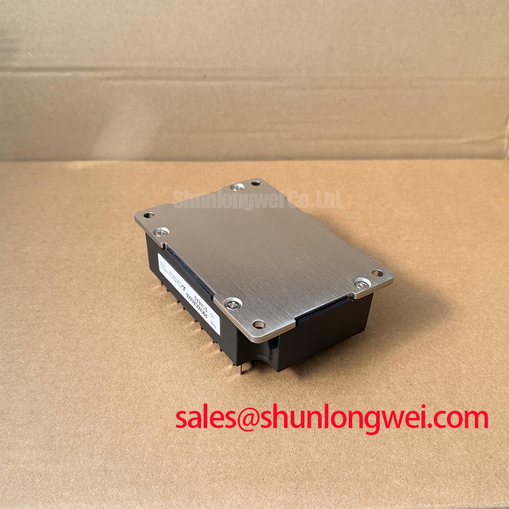
Before routing a replacement control board or revising an inverter assembly, engineers should verify the original PM300CBS060 terminal assignment from the equipment documentation and mating connector arrangement. An auxiliary emitter return, where provided by the module interface, should not be treated as a continuation of the main high current emitter path. Its purpose in the drive loop is to provide the gate control reference with a quieter emitter potential than a shared power return can provide during fast current transitions.
Shared emitter inductance can alter the effective gate emitter voltage during turn on and turn off. In practical terms, current flowing through a common return path can create a voltage disturbance that appears in the gate loop. That disturbance may contribute to gate ringing, inconsistent switching behavior between phases, or protection signals that do not reflect the intended switching state. This is a Design Consideration, not an additional official PM300CBS060 parameter.
A disciplined layout keeps the gate command path and its designated emitter reference together, while the main collector and emitter conductors carry load current through the shortest practical route. The objective is to minimize shared loop area where load current and gate reference current would otherwise interact. The inverter designer should inspect copper routing, busbar overlap, control connector pin assignment, and the point where low voltage control ground is referenced to the power stage. Clearance and creepage must be checked against the assembled drive voltage, pollution environment, enclosure conditions, and applicable equipment standard rather than copied from another inverter platform.
During repair work, a module that repeatedly shows abnormal gate waveforms does not automatically indicate a device fault. Inspect the auxiliary return continuity, connector contact pressure, board cracking around power terminals, and the condition of any local gate drive components. Compare the relevant gate emitter waveform and collector emitter waveform against a known good phase only with measurement equipment rated and connected appropriately for the inverter voltage. Oscillation can arise from multiple interacting causes, including layout changes, damaged control wiring, unsuitable probing practice, or an upstream driver problem.
For a heavy duty variable frequency AC motor drive, the 600V collector emitter rating establishes a firm device boundary, while the permissible bus voltage and transient margin must be validated at system level. Keep the power commutation loop compact to suppress inductive turn off overshoot, then verify peak voltage margins against the DC link voltage during controlled switching tests. 💡 Pro Tip: De energize and confirm the DC link is discharged before inserting or removing control connections near the module.
Where a compatibility review requires a same current class reference, the CM300DXDX1-24A can be reviewed as a separate module reference, but mechanical interface, internal configuration, drive requirements, protection behavior, and thermal design must be confirmed from the equipment documentation before any substitution decision.
Assembly Integrity & Layout Architecture: Implementing Symmetrical Busbar Geometry for High Current PM300CBS060
At 300A DC collector current at TC = 25°C, conductor geometry is part of the electrical design. Before tightening power hardware, compare the installed busbar orientation with the original drive assembly and inspect whether each phase uses equivalent conductor width, stack order, contact area, and return routing. A visibly similar connection can still create unequal resistance or inductance if one current path is longer, has a different bend radius, or shares a different portion of the DC link loop.
The typical 1.8V VCE(sat) at 300A is an official static condition, not a complete prediction of inverter loss. The positive temperature tendency commonly associated with IGBT conduction behavior can assist steady state current sharing in parallel arrangements, but it cannot ensure dynamic current balance. Dynamic sharing also depends on matched gate loop behavior, equal main current paths, synchronized drive commands, and equivalent cooling conditions. This is a Design Consideration for engineers evaluating parallel power paths.
Busbars should be assembled onto clean, flat contact surfaces with fastening hardware and torque controlled according to the inverter manufacturer’s mechanical documentation. The PM300CBS060 official parameter set supplied here does not specify terminal screw size or fastening torque, so no module specific torque value should be inferred. A vibration resistant assembly process should include inspection for uneven contact, relaxed fasteners, terminal deformation, and conductor movement that could transfer mechanical load into the module terminals.
The baseplate must also mate evenly to the specified heatsink. A thin, uniform thermal interface layer is generally used to fill microscopic surface irregularities, but the appropriate material, application method, and thickness are determined by the original drive thermal stack and its assembly instructions. Excess material can impede heat transfer; insufficient or uneven coverage can create localized thermal resistance. After installation, validate baseplate temperature sensing behavior and confirm that airflow, coolant flow, fan operation, or heat exchanger performance matches the equipment’s expected operating condition.
The typical baseplate over temperature protection level of 110°C is an official PM300CBS060 characteristic. It should be treated as a protection reference, not as a normal operating target or a substitute for thermal validation. A drive can experience junction temperature variation that is not fully represented by a single baseplate measurement, especially where load profiles, switching losses, heatsink condition, and ambient temperature differ from the original system assumptions.
Field Diagnostics & Commissioning: Fault Clearing Dynamics: Type I and Type II Desaturation in PM300CBS060 Topologies
Commissioning should begin with a non energized continuity and insulation check of the assembled inverter, followed by controlled low energy verification of the gate drive and fault output paths. The PM300CBS060 is an intelligent power module, but the supplied official specifications do not define a desaturation threshold, fault blanking interval, short circuit withstand time, or a Type I or Type II protection sequence. Those values must be obtained from the relevant Mitsubishi Electric module documentation and the original drive controller design before a protection timing decision is made.
In gate driven power stages, desaturation monitoring is generally used to identify an abnormal rise in collector emitter voltage while a switching device is commanded on. The protection chain may need to distinguish a transient switching interval from a sustained fault indication. A rapid hard turn off during fault current can produce a high inductive voltage excursion, so many inverter protection architectures use a controlled or staged turn off response. The applicable response must be determined by the complete gate drive, DC bus layout, clamp strategy, motor cable characteristics, and validated safe operating behavior of the installed module.
For service diagnostics, record the order of events rather than assuming a single failure cause. Determine whether the controller first reports gate drive undervoltage, over temperature, overcurrent, DC bus irregularity, phase current imbalance, or a module related fault output. Check whether the fault occurs during motor acceleration, regenerative deceleration, steady torque, or immediately after enable. This evidence helps separate a control sequencing issue from a power loop or load related condition.
Bootstrap supply integrity also deserves inspection where the host topology uses floating high side drive supplies. The bootstrap capacitor and charging path must provide stable drive bias across the operating duty cycle, while the charging diode and related components must tolerate their actual repetitive electrical stress. The Mitsubishi DIPIPM™ Bootstrap Circuit Design note provides useful general context for reviewing bootstrap behavior, although its circuit guidance must not be assumed to be a PM300CBS060 specific implementation.
An Engineering Recommendation is to capture gate command, fault status, phase current, and DC bus voltage together during a controlled fault investigation. This permits the system engineer to assess whether the protection reaction is coordinated with the observed electrical event. Detailed principles for low inductance gate control and measurement aware verification are also discussed in Precision Gate Drive Design.
Field Diagnostics & Commissioning: DC Bus Operating Voltage Headroom Derating in PM300CBS060 Topologies
The PM300CBS060 has an official collector emitter voltage rating of 600V. This rating should be checked against the actual DC bus operating range, normal regeneration behavior, supply tolerance, switching overshoot, and fault transient conditions measured in the specific inverter. A voltage rating alone does not establish an allowable DC bus setpoint because the installed system determines the voltage excursion at the module terminals.
Higher installation altitude can alter thermal conditions, enclosure cooling behavior, and system insulation coordination. Claims about terrestrial neutron exposure, single event burnout behavior, or failure in time rates require manufacturer qualification data or a cited reliability study applicable to the exact device and operating condition. No such quantitative reliability or altitude derating figure is stated in the supplied PM300CBS060 official specification. Engineers should therefore treat altitude related evaluation as a Design Consideration and apply the requirements of the complete equipment standard, site conditions, and qualified system design review.
For a heavy duty variable frequency AC motor drive, commissioning should include observation of DC bus behavior during acceleration, load reversal, regenerative events, and commanded stopping. Check the DC link capacitor condition, braking path operation where present, incoming supply stability, and motor cable routing before assigning excessive bus voltage to the module. Switching overshoot should be measured at a representative operating point using a suitable high voltage measurement method, with probe connections arranged to avoid adding misleading loop inductance.
Insulation coordination also requires system level attention. The official 2500V AC for 1 minute isolation voltage identifies the module’s stated isolation withstand condition; it does not certify the assembled inverter for a particular EMC, safety, surge, altitude, or end equipment compliance requirement. Verify enclosure spacing, busbar insulation, heatsink grounding arrangement, connector insulation, and protective earth continuity according to the applicable equipment standard and original drive architecture.
When evaluating the freewheel path and its thermal contribution, use the specific inverter schematic and module documentation rather than assuming an external diode arrangement. Mitsubishi Electric’s Diode Modules Lineup is useful for general product family context, but it does not define the PM300CBS060 internal configuration or establish a replacement topology. The system integrator should verify each semiconductor path, control interface, and protection connection from the original equipment documentation before energizing the repaired drive.