Content last revised on September 16, 2026
Field Diagnostics & Commissioning: Kelvin Emitter Connection in PM300CLA060 Topologies
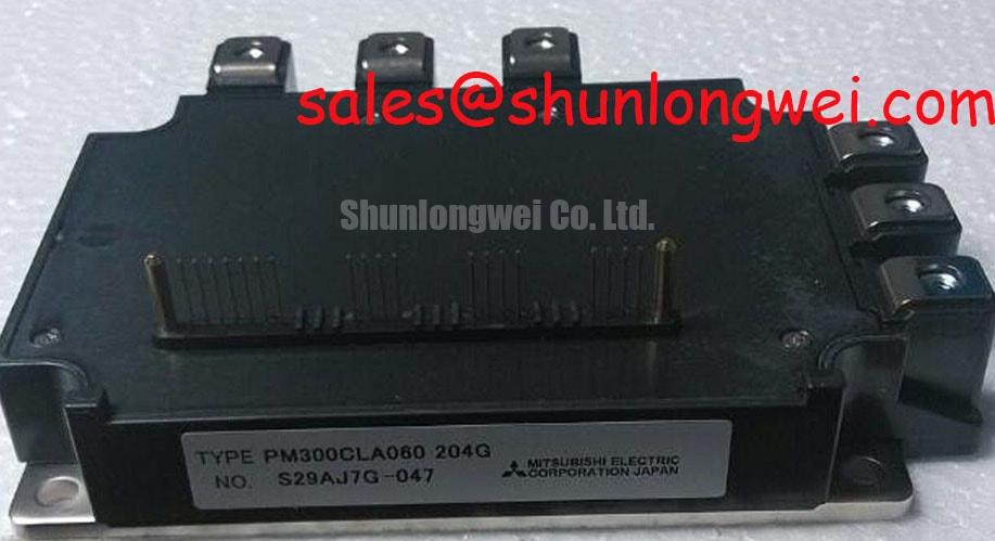
With the equipment fully isolated from its DC bus, first verify the module nameplate against the inverter documentation and inspect terminal hardware, busbar contact faces, insulation barriers, and heat sink seating before reconnecting any control wiring. The PM300CLA060 is a Mitsubishi Electric intelligent power module with an official 600 V collector-emitter voltage rating, 300 A rated collector current under specified conditions, and integrated fault logic covering overcurrent, short circuit, overtemperature, and undervoltage. These ratings define the module identity; they do not replace verification of the surrounding inverter, gate drive interface, or protection settings.
In a traction inverter or material handling drive, unstable switching behavior can originate outside the power module. A control return that shares part of the main emitter current path can pick up voltage created by changing load current. This can distort the effective gate-emitter voltage seen by the switching device, which may contribute to ringing, inconsistent current transitions, or protection events that appear intermittent. Where the original inverter topology provides an auxiliary emitter or Kelvin return connection, preserve its intended separation from the high-current emitter path. The system integrator should verify terminal allocation and connection requirements from the original equipment documentation before making changes.
🔧 Bench Diagnostic: Disconnect stored energy and confirm the DC link is safely discharged before moving control or power conductors around the module terminals.
During recommissioning, inspect the control harness for damaged insulation, strained crimps, loose plugs, and routing that places low-level control conductors beside the main switching loop. Probe gate-related signals only with a measurement arrangement appropriate for the inverter’s isolation requirements, then compare the observed waveform with a known-good phase or with the original service procedure. A waveform anomaly may indicate shared return impedance, grounding interaction, or a driver supply issue; it should not be treated as proof of a single failed part.
For equipment repair planning, confirm whether the installed power stage requires the same mechanical terminal arrangement, electrical ratings, protection interface, and control architecture. Where the repair documentation identifies it as compatible, CM300DXDX1-24A can be evaluated as a possible alternative. Compatibility remains an equipment-level decision requiring verification of electrical connections, cooling arrangement, control signals, and protection behavior.
The official electrical boundary of the PM300CLA060 is especially relevant when evaluating low-voltage forklift traction systems. A traction battery system may be described as low voltage at vehicle level, yet inverter commutation, regenerative braking, cable inductance, and switching transitions still demand controlled DC-link behavior. The module is rated at VCES = 600 V and IC = 300 A DC under specified conditions. Confirm the actual measured bus behavior and the inverter’s original protection thresholds rather than assuming that a nominal battery voltage describes the complete switching environment.
Assembly Integrity & Layout Architecture: Implementing Overvoltage Trip Prevention via Fast Switching for PM300CLA060
Start assembly by removing old thermal compound residue from the heat sink and checking that the mounting plane is clean, flat, and free of raised debris. The PM300CLA060 has an official isolation voltage specification of 2500 V AC for 1 minute at 60 Hz. This is an official module rating under the stated test condition, not a statement about the insulation capability of the assembled inverter, contaminated heat sink, cable system, or completed equipment.
A controlled thermal interface is central to repeatable service work. As a Design Consideration, a thin and uniform thermal interface material layer is commonly targeted in the approximate 50 to 80 μm range when the material supplier, mounting surfaces, and assembly procedure support it. The purpose is to fill microscopic surface irregularities while avoiding excessive thickness that increases thermal resistance. This is not an official PM300CLA060 factory requirement. The maintenance procedure and thermal material documentation should govern the final process.
Use the module manufacturer’s mechanical drawing and the equipment service instructions to establish fastener specification and torque. Tighten mounting points progressively in a cross pattern so contact pressure develops evenly across the module base. Do not infer a thread size or torque from another inverter platform. After initial thermal operation, a plant maintenance routine can include checking for contact temperature changes, degraded cooling airflow, blocked heat sink fins, and signs that the thermal interface has aged or been disturbed during previous service.
During motor deceleration, the traction motor can return energy to the DC link. The braking arrangement must provide a controlled path for that energy when the original inverter architecture requires it. Designers should review the braking transistor, ballast resistor, sensing path, and control logic as one system. A braking transistor or resistor selected without confirming regenerative energy, duty cycle, cooling capacity, and trip coordination can move the stress rather than resolve it. The PM300CLA060 protection functions are valuable at module level, but they do not substitute for validating the energy handling capability of the DC link and braking network.
Fast switching can expose weak assembly details. Busbar joints with uneven clamping, oxidized contact faces, or unsupported heavy conductors may create localized heating and variable impedance. Inspect the DC positive and negative paths, phase connections, and any braking connection with the inverter de-energized. When an overvoltage-related trip is reported, record operating mode, battery condition, payload, direction changes, and whether the event occurs during deceleration or acceleration. This evidence supports a disciplined test sequence instead of replacing components on the basis of a single symptom.
In systems with a separate rectifier or complementary power stage, interaction across the DC link deserves the same attention as the inverter module itself. The CM100DY-12E is a related power device that can be considered when reviewing compatible rectification or supporting converter stages, subject to the original circuit requirements and complete electrical verification.
Preventing Spurious Faults: DC Bus Low-Inductance Laminated Busbar Design Guidelines for PM300CLA060
Examine the DC bus layout from the module terminals back to the local capacitor bank before altering gate drive settings. During turn-off, the peak voltage is influenced by DC-link voltage plus the voltage generated by stray inductance and changing current. In practical terms, reducing loop inductance helps suppress turn-off overshoot, but the required result must be established through switching tests that verify peak-voltage margin against the actual DC-link condition. This is an Engineering Recommendation, not an official PM300CLA060 layout specification.
A laminated busbar can reduce loop area by keeping positive and negative DC conductors closely coupled across the relevant switching path. Symmetrical planar geometry also helps make the phase paths more consistent. Avoid treating a published inductance target from another platform as a universal requirement. Busbar stackup, capacitor placement, conductor length, module arrangement, current transition rate, measurement method, and allowable voltage margin are system-determined. A repair team should preserve the original conductor order and capacitor position whenever possible before assessing a redesign.
Local DC-link capacitors, snubber capacitors, and surge suppression components have different roles. A capacitor placed near the switching loop can reduce the effective inductive path seen during fast current changes. A metal-oxide varistor may assist with transient energy management where the original circuit uses one, but its clamping behavior, energy capability, aging characteristics, and coordination with other suppression components must be assessed at equipment level. It should not be assumed that adding a MOV alone resolves switching overshoot or nuisance fault behavior.
When a drive reports unexplained overcurrent, short-circuit, or undervoltage events, examine the measurement evidence in context. A disturbed laminated busbar, an aged capacitor bank, a loose sensing conductor, or a control supply issue can each affect observed behavior. Compare phase current traces and DC-bus waveforms against a known-good system where available, using suitable high-voltage differential measurement methods. The integrated OC, SC, OT, and UV fault logic is an official feature set, yet the exact response in a finished inverter depends on the host controller and associated circuitry.
For technicians comparing resonant and hard-switched converter behavior during fault reproduction or power-stage review, Resonant Topologies in Home Appliances provides a useful reference on topology-dependent switching conditions. The principles should be applied only after confirming that they correspond to the equipment under test.
Bootstrap and driver supply integrity also deserve inspection because an undervoltage event can arise from the local driver supply path rather than from the main DC source. Mitsubishi Electric’s DIPIPM™ Bootstrap Circuit Design note provides useful background for reviewing bootstrap circuit behavior. Control loop response should likewise be assessed from measured evidence; the relationship between transfer function and loop gain is described in this transfer function reference.
PM300CLA060 Thermal Electrical Optimization: Multi-Module Parallel Current Sharing Practical Tuning
Before considering parallel operation, establish whether the original drive was designed, validated, and protected for multiple modules. The PM300CLA060 official voltage and current ratings identify one module as 600 V and 300 A under specified conditions; they must not be multiplied to create an assumed system rating. Parallel current sharing depends on matching static conduction behavior, switching timing, busbar geometry, cooling conditions, driver paths, protection coordination, and the converter control strategy.
The relationship between collector-emitter saturation voltage and temperature can assist steady-state current sharing in some IGBT operating regions because of the positive temperature coefficient commonly associated with the device characteristic. This is a Design Consideration, not a guarantee that any set of modules will share current equally. Dynamic sharing is often more sensitive to differences in gate-loop impedance, emitter return paths, and commutation-loop geometry. Route equivalent gate and return paths symmetrically, and keep corresponding DC and phase conductor paths mechanically comparable.
The PM300CLA060 datasheet lists collector-emitter saturation voltage as 1.6 V typical and 2.1 V maximum under specified test conditions. Use these values only in the stated official specification context and verify the original datasheet test conditions before using them in a loss calculation. Actual in-circuit dissipation changes with current, temperature, switching conditions, modulation, cooling, and load duty. A measured temperature difference between parallel positions may indicate unequal cooling, unequal electrical path resistance, variation in control timing, or a combination of factors.
For practical tuning, bring the equipment up through the approved commissioning method and observe each module position under controlled load changes. Verify that current sensing, overcurrent protection, and thermal monitoring respond correctly before extending operation. If one position shows a persistent difference, inspect mounting contact, thermal material distribution, busbar symmetry, gate wiring, sensor routing, and driver supply stability. Changes should be documented one at a time so their effect can be confirmed.
Preventive maintenance should include cleaning restricted heat sink airflow, inspecting fan condition where fitted, checking for moisture or condensation exposure, reviewing terminal tightness against the equipment procedure, and examining thermal interface condition during scheduled power-stage service. These actions support reliable operation without making unsupported claims about operating life, failure rate, EMC compliance, altitude capability, or system certification.