

Content last revised on September 10, 2026
CM300E3U-12H IGBT: Data-Driven Insights for Brake Circuits
Engineering Analysis of the Mitsubishi CM300E3U-12H IGBT Module
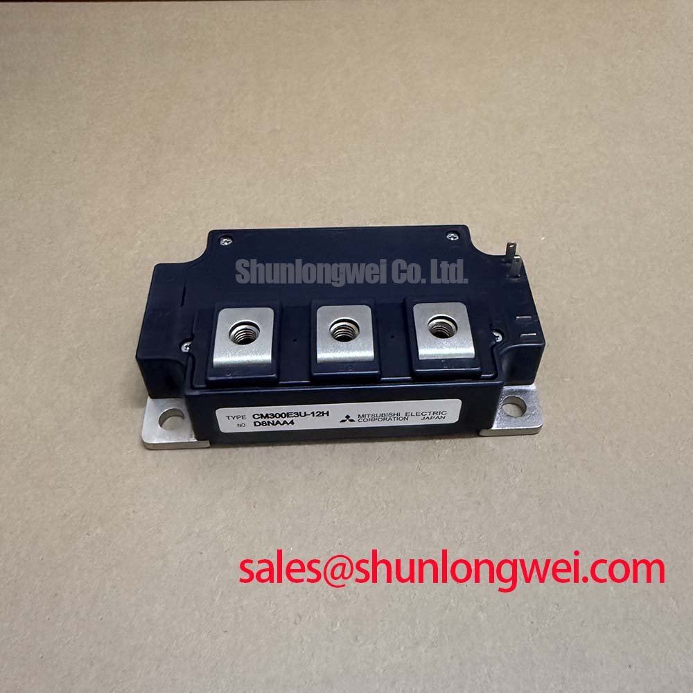
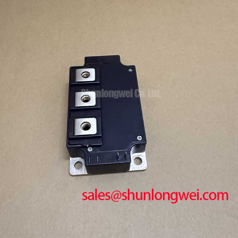
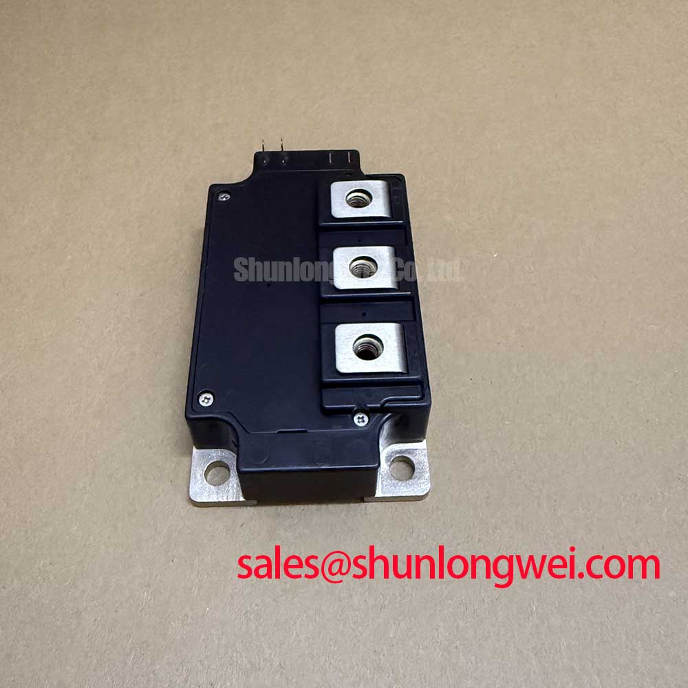
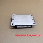
The Mitsubishi CM300E3U-12H is a high-power IGBT module engineered for robust performance in demanding switching applications, particularly dynamic braking circuits. Its design centers on delivering low conduction losses and high-frequency operation while ensuring straightforward thermal management. With core specifications of 600V | 300A | VCE(sat) 2.2V typ., this module provides a thermally efficient and electrically stable solution. Key engineering benefits include low drive power requirements and a simplified system assembly due to its isolated baseplate. For engineers designing DC motor controls or boost regulators, a critical consideration is managing the energy dissipated during braking; this module's integrated free-wheeling diodes and low saturation voltage directly address this challenge by minimizing power loss within the switch itself.
Frequently Asked Questions (FAQ)
What is the primary advantage of the CM300E3U-12H's internal configuration?
The module contains a single IGBT with a reverse-connected, super-fast recovery free-wheel diode. This monolithic design is optimized for chopper or brake circuits, simplifying the external component count and reducing stray inductance, which is a common challenge in high-frequency switching designs.
How does the isolated baseplate affect thermal design?
The electrically isolated baseplate streamlines thermal integration. It allows the module to be mounted directly to a common heatsink with other components without requiring separate insulating layers. This not only simplifies assembly but also promotes more effective and predictable heat transfer, a critical factor for long-term operational reliability.
What does a typical VCE(sat) of 2.2V mean for my application?
Collector-Emitter Saturation Voltage, or VCE(sat), is analogous to the 'on-state resistance' of the switch. A lower VCE(sat) indicates less voltage drop across the IGBT when it is fully conducting. With a typical VCE(sat) of 2.2V at 300A, the CM300E3U-12H directly translates to lower conduction losses (Power Loss = VCE(sat) * Ic), meaning less heat is generated and overall system efficiency is improved. For an in-depth exploration of this parameter, see our guide on decoding IGBT datasheets.
Application Scenarios Focused on Braking and Control
The CM300E3U-12H is purpose-built for high-power DC switching environments where energy management and rapid control are paramount. Its features directly support the following applications:
- Dynamic Braking Resistor Circuits: In motor drives for elevators, cranes, or conveyors, kinetic energy must be dissipated quickly during deceleration. This module acts as a high-speed switch to divert motor-generated current through a braking resistor, providing controlled and powerful braking torque.
- DC Motor Controls: For large-scale DC motor applications, the module's 300A current rating and low conduction losses ensure efficient power delivery and control, minimizing thermal stress on the system.
- Boost Regulators: In high-power DC-DC converters, the module's ability to operate at high frequencies (15-20kHz) allows for the use of smaller magnetic components, contributing to more compact and cost-effective system designs.
For applications demanding higher voltage blocking, such as those in large-scale industrial drives, the CM300DY-24H offers a 1200V Vces rating in a dual-IGBT configuration.
Technical Deep Dive: Electrical and Thermal Characteristics
A granular look at the datasheet reveals the engineering trade-offs made to optimize the CM300E3U-12H for its intended use. The collector-emitter breakdown voltage (VCES) of 600V provides a sufficient safety margin for systems operating on 200-240V AC lines. The peak collector current (ICM) is rated at 600A, allowing the device to handle transient current spikes that are common in motor braking scenarios without immediate failure, provided the junction temperature remains within its safe operating area.
From a thermal perspective, the maximum collector dissipation (Pc) of 890 Watts at a case temperature of 25°C is a critical metric. This figure serves as the foundational data point for heatsink selection and thermal interface material choice. Effective thermal management is not merely about preventing failure; it is about ensuring the module operates at a temperature that maximizes its lifespan and maintains stable electrical characteristics.
Deployment Considerations for System Integrators
Integrating the CM300E3U-12H requires attention to both mechanical and electrical details to ensure system reliability. The module specifies a mounting torque of 3.5 to 4.5 N·m for both the M6 main terminals and the mounting holes. Adhering to these torque specifications is essential to establish a low-resistance electrical connection and an effective thermal path to the heatsink. Overtightening can cause mechanical stress and damage the isolated substrate, while undertightening can lead to high contact resistance and localized overheating.
Comparative Data for Informed Decision-Making
To assist engineers in the evaluation process, this table provides a factual comparison based on key datasheet parameters. This information is intended to support, not guide, your selection process.
| Part Number | Configuration | VCES (Collector-Emitter Voltage) | IC (Continuous Collector Current) | VCE(sat) Typ. @ IC |
|---|---|---|---|---|
| CM300E3U-12H | Single Chopper | 600V | 300A | 2.2V @ 300A |
| CM300HA-12H | Single IGBT | 600V | 300A | 2.2V @ 300A |
| CM300DU-12H | Dual IGBT (Half-Bridge) | 600V | 300A | 2.2V @ 300A |
Note: The data presented is based on publicly available datasheets. Engineers should consult the official documents for the most current and complete specifications.
The Strategic Value of Specialized IGBTs in Modern Drives
As industrial automation continues to advance, the demand for more precise, efficient, and reliable motor control intensifies. The move towards specialized IGBT Module configurations like the chopper/brake topology found in the CM300E3U-12H reflects a broader industry trend. Rather than using generic half-bridge modules for every function, designers can leverage purpose-built components to optimize performance and reduce system complexity. This approach aligns with the principles of lean design, where each component is selected to perform its role with maximum efficiency, contributing to a lower total cost of ownership and enhanced system robustness over the lifecycle of the equipment.
Key Technical Specifications
The following parameters are critical for design and simulation when evaluating the CM300E3U-12H for your application.
| Parameter | Value |
|---|---|
| Collector-Emitter Voltage (VCES) | 600 V |
| Collector Current (IC) @ Tc = 25°C | 300 A |
| Collector-Emitter Saturation Voltage (VCE(sat)) Typ. | 2.2 V |
| Gate-Emitter Voltage (VGES) | ±20 V |
| Maximum Collector Dissipation (Pc) @ Tc = 25°C | 890 W |
| Junction Temperature (Tj) | -40 to 150 °C |
| Isolation Voltage (Viso) | 2500 Vrms |
For complete details, please refer to the official CM300E3U-12H datasheet.
The strategic deployment of application-specific modules like the CM300E3U-12H enables engineers to build more efficient and reliable power conversion systems. By focusing on components whose characteristics are precisely aligned with functional requirements, such as braking or boost regulation, designers can enhance overall system performance and create more competitive end-products that are ready for the demands of next-generation industrial applications.