

Content last revised on June 30, 2026
The Engineering Edge in High-Frequency Power Conversion
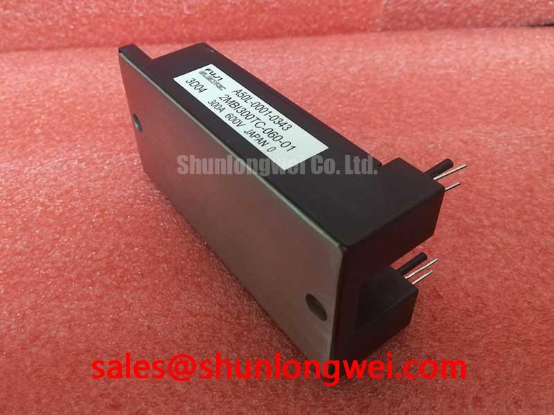
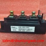
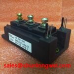
2MBI300TC-060: Dual IGBT Module Engineered for Switching Efficiency
Engineered for demanding, high-frequency power conversion, the Fuji Electric 2MBI300TC-060 is a 600V dual IGBT module that provides a robust solution for minimizing switching losses and enhancing thermal performance. With key specifications of 600V | 300A | VCE(sat) 2.1V typ., this module delivers tangible benefits in system efficiency and reliability. It is optimized for applications where both low conduction losses and fast switching are critical design parameters. For systems requiring higher current handling within a similar operational voltage, the 2MBI400TA-060 provides an increased current rating. Best fit for industrial inverters and motor drives operating at elevated PWM frequencies, this module enables designers to achieve higher power density and reduce heatsink requirements.
Application Scenarios & Value
Achieving System-Level Benefits in High-Frequency Motor Drives
The 2MBI300TC-060 is specifically designed for high-performance power control systems such as industrial Variable Frequency Drives (VFDs), servo drives, and power supplies for welding equipment. In these applications, a primary engineering challenge is managing the heat generated by switching losses, which escalate with frequency. The module's design directly addresses this by optimizing its switching characteristics, including turn-on and turn-off energy. This allows for higher operating frequencies without thermal runaway, enabling the use of smaller, lighter magnetic components and reducing the overall system footprint. The result is a more compact, efficient, and reliable power stage, critical for modern automated systems.
Key Parameter Overview
Decoding the Specs for Enhanced Switching Performance
The technical specifications of the 2MBI300TC-060 are tailored for efficiency and reliability in dynamic load environments. The values presented below are key indicators of its performance in target applications.
| Parameter | Symbol | Conditions | Value |
|---|---|---|---|
| Absolute Maximum Ratings (Tc=25°C) | |||
| Collector-Emitter Voltage | VCES | - | 600V |
| Continuous Collector Current | IC | Tc=80°C | 300A |
| Pulsed Collector Current | ICP | 1ms pulse | 600A |
| Gate-Emitter Voltage | VGES | - | ±20V |
| Max. Junction Temperature | Tj max | - | 150°C |
| Electrical Characteristics (Tj=25°C) | |||
| Collector-Emitter Saturation Voltage | VCE(sat) | IC=300A, VGE=15V | 2.1V (Typ.), 2.6V (Max.) |
| Forward Voltage (FWD) | VF | IF=300A, VGE=0V | 1.9V (Typ.), 2.4V (Max.) |
| Gate Threshold Voltage | VGE(th) | IC=300mA, VCE=10V | 5.5V to 8.5V |
Note: The parameters listed are summary values. For detailed specifications, characteristic curves, and thermal information, please refer to the official datasheet.
Technical Deep Dive
A Closer Look at Low VCE(sat) and its Impact on Conduction Losses
A defining feature of the 2MBI300TC-060 is its low Collector-Emitter Saturation Voltage (VCE(sat)), specified at a typical value of 2.1V at its nominal 300A rating. This parameter is fundamental to the module's efficiency, particularly in applications with high duty cycles. Think of VCE(sat) as the "resistance" the switch presents when it is fully turned on. Just as a partially closed valve restricts water flow and creates pressure loss, a higher VCE(sat) causes a larger voltage drop across the IGBT, dissipating more energy as heat (Power Loss = VCE(sat) × IC). By achieving a low VCE(sat), this IGBT Module directly reduces these conduction losses. This reduction in waste heat not only boosts overall energy efficiency but also simplifies thermal management, potentially allowing for a smaller heatsink or a higher power output within the same thermal design envelope.
Frequently Asked Questions (FAQ)
How does the 2.1V typical VCE(sat) of the 2MBI300TC-060 benefit my design?
A low VCE(sat) directly translates to lower conduction losses during operation. This improves the overall energy efficiency of your system and reduces the amount of waste heat that must be managed by the cooling system, enabling more compact and cost-effective thermal designs.
What is the significance of the dual-IGBT (2-in-1) configuration?
The dual configuration integrates two IGBTs in a half-bridge topology within a single package. This simplifies the design of common circuits like single-phase inverters or one leg of a three-phase inverter, reducing component count, minimizing parasitic inductance, and simplifying the PCB layout and assembly process.
Is this module suitable for hard-switching applications?
Yes, the 2MBI300TC-060 is designed for hard-switching applications. Its datasheet provides detailed information on switching energy (Eon, Eoff) and reverse recovery characteristics of the freewheeling diode (FWD), which are critical for calculating and managing switching losses in such topologies.
For further design support or to explore component options for your power conversion project, our engineering team is available to assist with your requirements.