

Content last revised on September 24, 2026
Field Diagnostics & Commissioning: High-Frequency Switching Loss Dissipation in PT150S8 Topologies
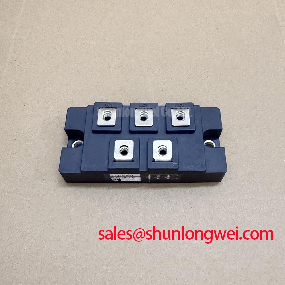
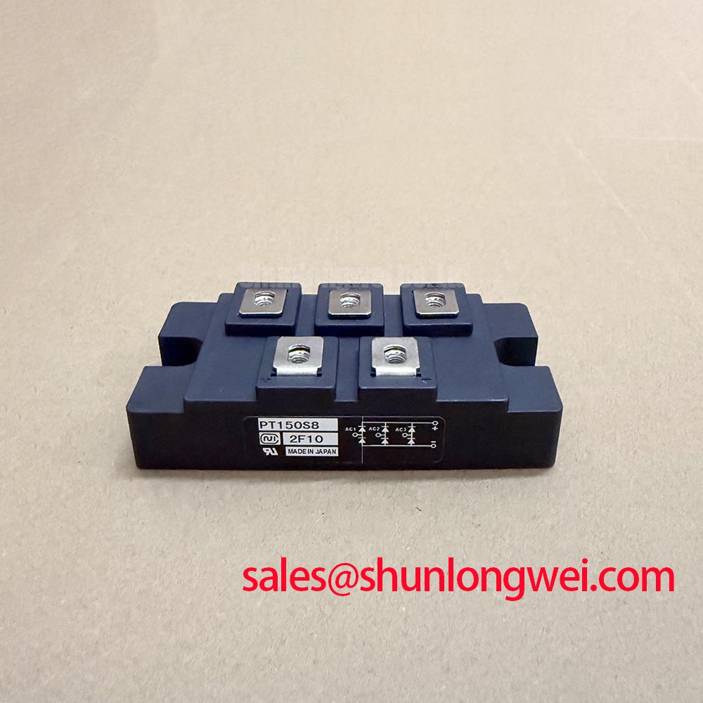
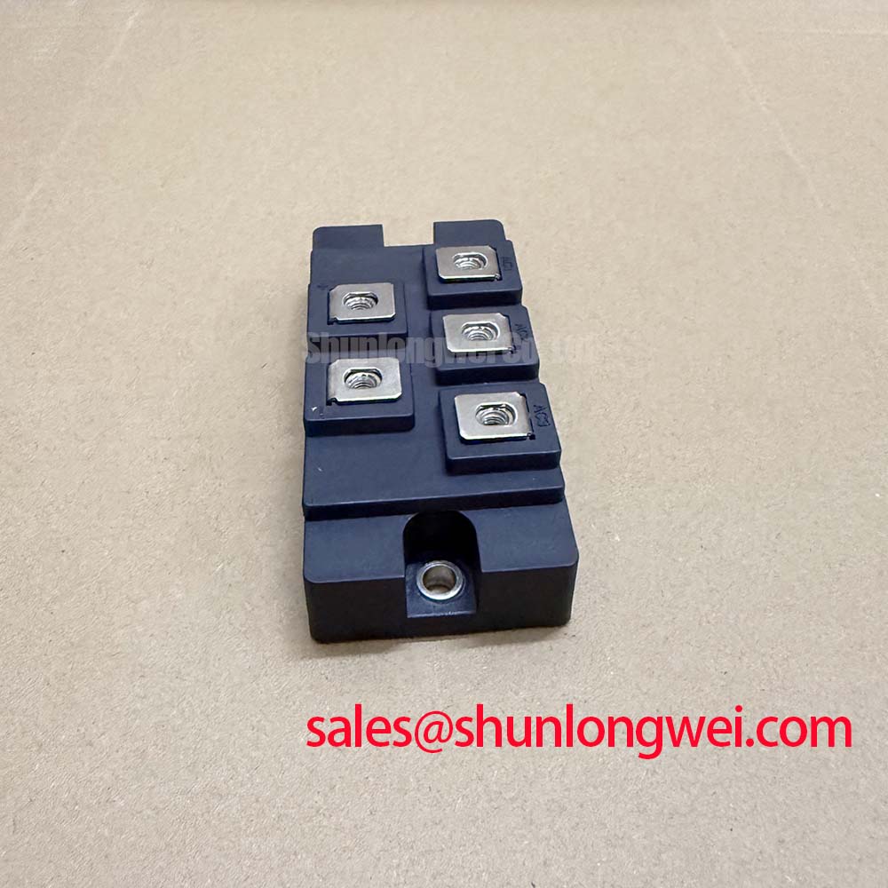
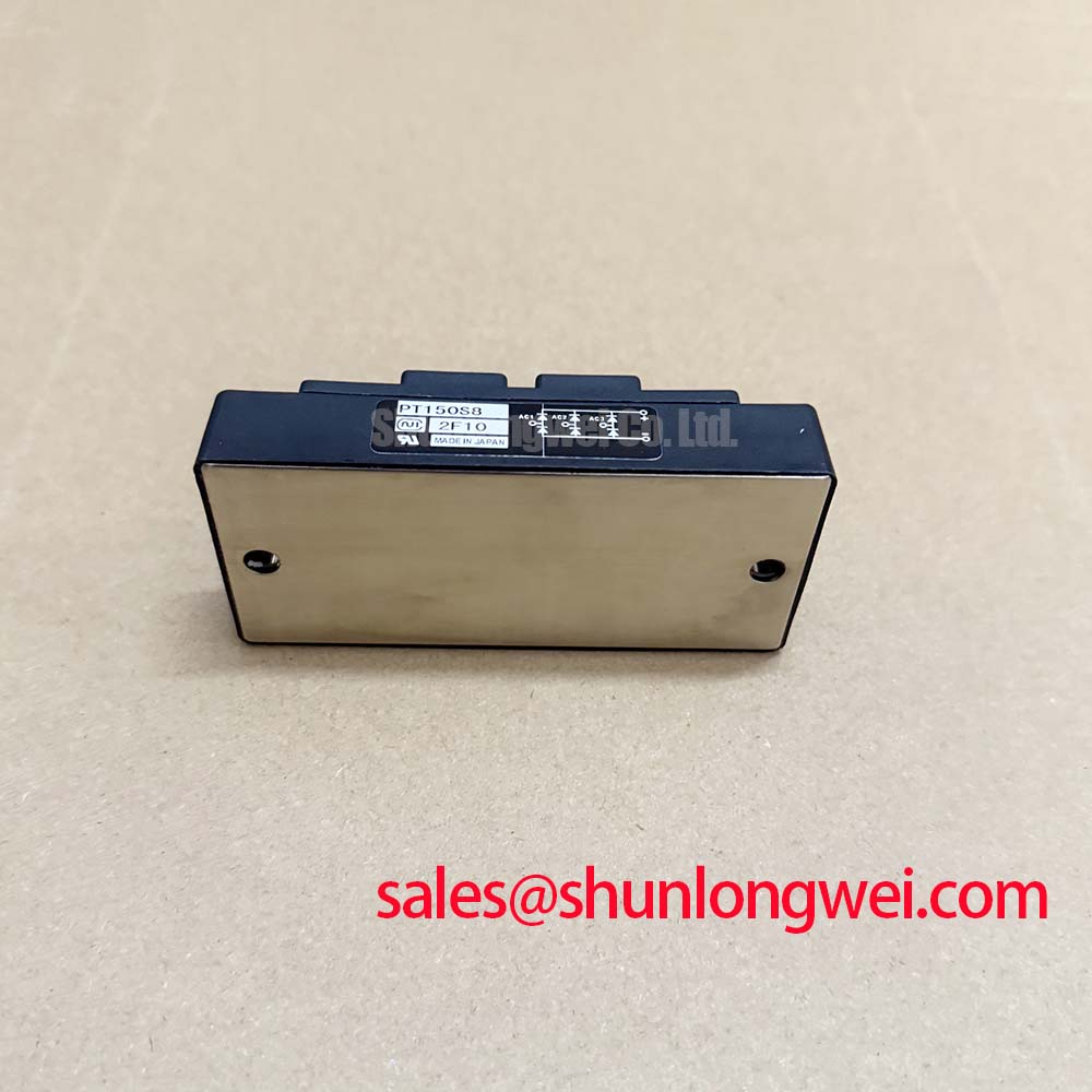
Start commissioning by isolating the equipment, checking the module marking against the approved bill of materials, and confirming that the circuit voltage and current remain within the PT150S8 official ratings of 650.0 V and 150.0 A. The device is specified as an Isolated Power Module from Nihon Inter (NIEC), with a product category of Thyristor / Diode Module. These are the confirmed factory parameters available for this product record; diode recovery data, fuse coordination values, terminal diagrams, thermal resistance, and installation torque must be verified against the applicable manufacturer documentation before commissioning.
For a high-voltage three-phase motor solid-state soft starter, the first practical inspection should cover the power terminals, conductor condition, insulating clearances, fuse assembly, and heatsink contact. A cold-state comparison between corresponding semiconductor paths can identify an open connection, an abnormal short condition, or an uneven phase path, but a resistance reading alone cannot certify the module. Use an approved isolation procedure and compare measurements with a known-good assembly or the original service documentation.
Reverse-recovery behavior is relevant when the diode section commutates current into another path. The engineering objective is to limit recovery-related current peaks, switching overshoot, and unwanted electromagnetic radiation without assigning an unsupported value to Irrm or trr. If the original datasheet provides those values, use them with the actual load current, commutation circuit, wiring inductance, and operating temperature. Otherwise, the system engineer should verify the switching waveform with a properly rated differential probe and current probe.
Fuse selection also requires more than matching the nominal module current. The semiconductor fuse must be coordinated with the prospective fault current, clearing time, and manufacturer-specified I2t capability. No fuse I2t value is supplied in the confirmed product data for this page, so the protection study should use the approved fuse table for the complete soft-starter assembly. Check phase symmetry after replacement and inspect whether a fuse operates because of an external short, a commutation problem, or a damaged semiconductor path.
The PT150S8 may be evaluated in a motor soft-starter topology where controlled conduction reduces the applied motor voltage during acceleration. Compatibility still depends on the electrical arrangement, bypass contactor, line protection, motor current, and controller firing strategy. A neutral comparison with another power module can be made using PGH50N16, but substitution should only proceed after voltage class, current duty, package geometry, gate or control requirements, and protection coordination are confirmed.
PT150S8 Circuit Protection & Reliability: Calibrating Harmonic Current Injection and Line Filter
When the PT150S8 is considered for a three-phase soft starter, the firing-angle range should be treated as a system-control variable rather than a guaranteed module operating profile. An evaluation from α = 0° through α = 150° can reveal how the controller changes the applied RMS voltage, motor current, displacement power factor, reactive power demand, and harmonic content. The correct transfer characteristic depends on the connected motor, line impedance, firing symmetry, bypass timing, and control-loop behavior.
Use a power-quality analyzer to record line-to-line voltage, phase current, RMS current, current crest factor, and harmonic spectrum during controlled acceleration. The RMS concept is central to conduction-loss assessment because resistive loss follows the effective current rather than a simple average reading. A general reference for RMS current treatment is available from Root Mean Square current calculations. This reference is an industry learning resource, not a PT150S8-specific factory specification.
Line-filter selection should begin with the measured disturbance profile. A filter that reduces conducted noise at one firing condition may influence displacement power factor, commutation behavior, or motor acceleration at another. Designers should verify filter impedance, damping, resonance risk, and voltage drop under the complete installation conditions. Avoid assigning a universal capacitor, reactor, or filter value to this module without the soft-starter schematic and measured line data.
The upstream rectification and protection chain should also be reviewed as a complete topology. The PK55FG120 can be considered as a neutral reference for an associated rectifier or complementary power stage, subject to its own specifications and the system voltage class. It should not be treated as an automatic companion or direct substitute for the PT150S8.
Reliability checks should include terminal temperature comparison between phases, inspection of fuse clips, verification of bypass contactor timing, and oscilloscope review of switching transients where appropriate. If harmonic current injection appears excessive, examine controller synchronization, phase imbalance, motor condition, line impedance, and filter interaction before attributing the behavior to the module. The confirmed PT150S8 data establishes a 650.0 V voltage rating and 150.0 A current rating; the equipment designer must establish operating margins from the actual duty cycle and transient measurements.
PT150S8 Operational Boundaries: Ensuring Uniform Heatsink Contact Pressure
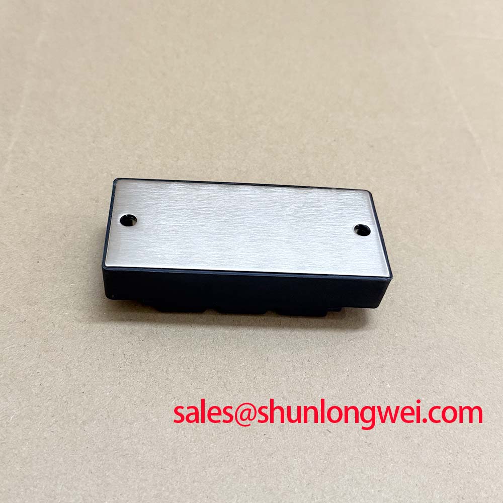
The isolated module format makes the mechanical interface part of the electrical reliability review. Before installation, inspect the heatsink surface for contamination, burrs, warpage, and old thermal-interface material. Clean the contact area using an approved process, then apply the interface material according to the heatsink and compound supplier instructions. The confirmed product record does not specify a PT150S8 junction-to-case thermal resistance, baseplate flatness tolerance, compound thickness, or mounting torque, so these values must come from the applicable mechanical drawing or manufacturer documentation.
Uniform contact pressure matters because local gaps increase thermal resistance while excessive or uneven force can distort the module case or stress the internal assembly. Tighten fasteners in the specified sequence and use a calibrated tool. If the original assembly uses multiple mounting points, record the sequence during removal so the replacement follows the same mechanical loading pattern. Do not infer a module-specific torque from a general fastener table.
Thermal evaluation should combine heatsink temperature, case temperature, phase current, switching duty, ambient conditions, and airflow. A single surface temperature measurement can miss a localized hot region. Infrared measurements require a suitable surface emissivity reference, while thermocouples should be attached without disturbing the mechanical interface. During load testing, increase duty progressively and compare the three phases under equivalent conditions.
⚠️ Maintenance Note: Inspect heatsink airflow and monitor phase-to-phase contact temperature during scheduled maintenance, especially after thermal-interface material aging, fan cleaning, or repeated service work.
Dust accumulation, blocked ventilation, moisture condensation, and repeated thermal cycling should be recorded as maintenance conditions rather than converted into unsupported lifetime predictions. For equipment installed in a high-voltage motor soft starter, verify enclosure sealing and anti-condensation provisions according to the complete cabinet design. The module itself should not be credited with an enclosure environmental rating unless that rating is stated in the applicable official documentation.
Where regenerative braking or a downstream braking function is present, the thermal review must include the pulse profile of the switching assembly and the energy absorbed by the braking resistor. The PT150S8 rating alone does not define the allowable braking energy, transient junction temperature, or heatsink requirement. Those limits must be established from the actual circuit, pulse duration, repetition rate, and manufacturer thermal data.
PT150S8 Thermal-Electrical Optimization: Saturable Reactor and Snubber Sizing for Practical Tuning
Snubber and reactor decisions should begin with measured switching waveforms rather than a preset component value. A voltage probe placed across the relevant semiconductor path can show turn-off overshoot, ringing, and suspected dv/dt-induced behavior. A current probe can then establish whether the disturbance is linked to commutation current, wiring inductance, filter resonance, or an external load event. The design objective is to limit peak electrical stress and oscillation while preserving the intended soft-start control response.
For an RC snubber, the resistor and capacitor are selected from the measured ringing frequency, transient energy, leakage current, voltage rating, pulse capability, and acceptable steady-state loss. These are system calculations, not confirmed PT150S8 factory parameters. The snubber must be checked at the highest expected line voltage and switching condition, with component insulation and pulse ratings suitable for the installation.
A series saturable reactor may be evaluated when the circuit requires controlled current rise during a short commutation interval. Its selection depends on the load current waveform, saturation behavior, available cabinet space, thermal dissipation, and interaction with the line filter. Designers should verify that the reactor does not create excessive voltage drop during acceleration or interfere with the bypass transition. The appropriate value must be established through the complete topology and bench testing.
Long motor cables introduce distributed inductance and capacitance that can produce reflected-wave voltage stress at the motor terminals. If the soft starter is connected through a long cable route, measure the cable-end waveform and assess the need for a filter or damping network. Do not assume that the PT150S8 voltage rating alone covers cable-reflection peaks; the system engineer must verify measured peak voltage against the semiconductor and motor insulation limits.
Gate or control-loop wiring, where applicable to the selected assembly, should be routed to minimize coupling with high-current conductors. Keep the control return path defined by the original circuit design and inspect connectors for looseness, oxidation, and contamination. Any damping adjustment should be treated as a typical starting point for bench tuning, followed by verification of trigger timing, phase balance, turn-off behavior, and thermal performance.
For structured fault analysis and semiconductor operating principles, engineers can consult The Ultimate IGBT Knowledge Base. The reference provides broader power-semiconductor context; the PT150S8 application decision still depends on the NIEC documentation, the actual soft-starter schematic, measured transients, and the approved protection design.