

Content last revised on September 23, 2026
PT76S16 Operational Boundaries: Evaluating Dynamic Voltage Sharing and RC Damping in Limits
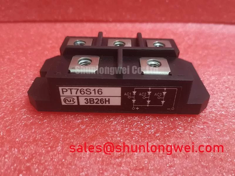
The PT76S16 is listed by Nihon Inter (NIEC) as an isolated power module in the thyristor and diode module category. Its stated ratings are 1200.0 V voltage and 75.0 A current. These are official product specifications for identification and system review; they do not by themselves establish the allowable operating point for every cooling arrangement, firing condition, surge profile, or fault event.
| Parameter | PT76S16 Listed Specification | Engineering Use |
|---|---|---|
| Manufacturer | Nihon Inter (NIEC) | Confirm against the replacement documentation and equipment records |
| Device category | Thyristor / Diode Module | Evaluate for controlled rectification and power conversion assemblies |
| Voltage rating | 1200.0 V | Compare with the complete applied voltage, transient environment, and system insulation design |
| Current rating | 75.0 A | Review alongside conduction angle, heatsinking, waveform, duty cycle, and protection coordination |
| Package | Isolated Power Module | Verify mounting, isolation, terminal arrangement, and thermal interface requirements from the equipment documentation |
The available product information does not define a complete terminal drawing, gate trigger specification, thermal impedance network, fuse coordination table, or mounting torque value. The system integrator should verify those items from the original NIEC documentation or the equipment manufacturer’s service records rather than transferring values from another module family.
Before evaluating an RC snubber or a series saturable reactor, record the actual terminal designations and compare them with the known-good assembly. An isolated module package does not make the external circuit automatically interchangeable; the power terminals, gate terminals, auxiliary cathode references, and mechanical mounting arrangement must all match the original topology.
For a high-current DC rectifier, designers should examine commutation overlap, wiring inductance, transformer leakage, and the location of the snubber relative to the thyristor junction. An RC network can reduce unwanted voltage rise and ringing when selected for the measured switching waveform, but its resistance, capacitance, pulse energy, and voltage rating are system-determined. The PT76S16 specification supplied here does not authorize a universal Rs or Cs value.
Dynamic voltage sharing becomes especially important when several controlled devices operate in the same converter. Engineers should verify the voltage waveform at the module terminals with an appropriately rated differential probe, checking turn-off overshoot and repetitive ringing under the intended load. If a saturable reactor is considered, its saturation behavior must be assessed against the firing sequence, fault current, and thermal response of the complete rectifier.
Gate-loop layout also deserves direct inspection. Minimize parasitic loop area, keep the gate reference paired with its control return, and separate high-current commutation paths from sensitive firing wiring. These are Design Considerations, not PT76S16-specific factory guarantees. Gate trigger current, gate trigger voltage, pulse width, pulse repetition, and any negative gate bias used to reduce false triggering must be confirmed from the applicable gate-control documentation.
For comparative sourcing, engineers may also review the PGH50N16 as a separate module option. It should not be treated as an automatic substitute: voltage, current, terminal geometry, gate characteristics, isolation construction, thermal behavior, and protection coordination require a documented comparison.
Field Diagnostics & Commissioning: IEEE 61000-4-5 Industrial Surge Immunity in PT76S16 Topologies
Commissioning should begin with a de-energized inspection of the AC input protection path, semiconductor fuses, surge suppressors, snubber components, and control wiring. IEEE 61000-4-5 is a system-level surge immunity method; the PT76S16 itself must not be described as independently compliant with an equipment-level EMC test.
A MOV stage, line reactor, fuse, and RC network may each perform a different protection function. The correct MOV voltage class depends on the actual line-to-line and line-to-earth conditions, temporary overvoltage exposure, earthing arrangement, and expected surge environment. The correct component selection therefore remains a Design Consideration for the equipment designer. Verify the clamping behavior and energy capability against the measured installation conditions.
During a controlled startup, capture the gate-to-reference waveform and the main terminal waveform at the same time. An unexpected trigger can be associated with several conditions, including common-mode movement, inadequate return routing, excessive ringing, incorrect pulse timing, or a control reference that is not aligned with the module terminal definition. Confirm the signal path with the circuit schematic instead of assigning a single cause from the observed symptom.
Cold-state diode-mode testing can provide a useful incoming baseline, but it is not a complete semiconductor qualification test. Isolate the module from parallel resistors, snubber capacitors, transformers, and control boards before measuring. Record the meter polarity, terminal pair, ambient condition, and test instrument so later comparisons use the same setup. A reading that differs from a known-good module should lead to isolation testing and waveform verification rather than an unsupported pass or fail threshold.
💡 Bench Tip: Use ESD controls and compare cold-state measurements with a documented known-good reference before applying any powered gate or line test.
Where the rectifier feeds a high-current green hydrogen electrolyzer DC power supply, the complete enclosure, busbar, transformer, filter, and grounding arrangement must be reviewed as one system. The module’s 1200.0 V and 75.0 A listed ratings are identification boundaries, not a substitute for surge, creepage, clearance, or short-circuit validation.
PT76S16 Thermal-Electrical Optimization: Harmonic Current Injection and Line Filter Practical Tuning
In a phase-controlled rectifier, firing angle changes the average DC output, input current displacement, harmonic content, and reactive demand. The relationship is affected by source impedance, transformer leakage, commutation overlap, load type, control timing, and the number of pulses in the converter. Engineers should measure the actual line current and voltage rather than infer equipment performance from the module’s current rating alone.
Line-filter tuning should start with the unmodified rectifier waveform. Capture phase voltage, line current, gate timing, and DC output under representative load conditions. Look for resonance between the filter and the upstream transformer or cable network. A filter that improves one operating point can create excessive oscillation at another, so the final network should be validated across the planned firing-angle range and load envelope.
The PT76S16 package rating does not provide a thermal design by itself. The designer should verify the heat-spreader arrangement, interface flatness, mounting method, airflow or liquid-cooling conditions, and the transient thermal response of the complete assembly. Junction-temperature margin during short pulses and firing-angle changes must be calculated from the applicable manufacturer thermal data, which is not included in the supplied parameter set.
Thermal-electrical checks should include the actual conduction waveform. A 75.0 A rating cannot be interpreted as a universal continuous current value without the associated case temperature, cooling conditions, duty cycle, waveform, and manufacturer test method. During commissioning, compare module case temperature, terminal temperature, phase current balance, and bus ripple. Unequal readings may indicate an issue elsewhere in the converter, such as wiring resistance, gate timing, transformer imbalance, or cooling contact.
Control-loop measurements benefit from separating power-stage behavior from regulator behavior. The principles of transfer functions and loop-gain observation described in Transfer Function and Loop Gain Bode Analysis in Switch-Mode Regulators can help structure a measurement plan, but the cited theory does not provide PT76S16-specific control parameters. Current feedback may also use sensors based on different physical technologies; background on GMR and TMR sensors for industrial current measurement can support sensor-interface review without implying a particular sensor is built into this module.
Benchtop Waveform Tuning: Mitigating Stress via I2t Sub-Cycle Melting Rating on PT76S16
Short-circuit coordination must be established from the semiconductor’s applicable I2t withstand data and the selected semiconductor fuse’s clearing I2t. The supplied PT76S16 information does not include either value, so a numerical fuse pairing or dead-short survival claim would be unsupported. Obtain the relevant NIEC data and the fuse manufacturer’s time-current information before approving the protection scheme.
On the bench, inspect the fuse type, interrupting rating, physical location, busbar length, contact condition, and current-transformer or sensor response. Confirm that the protection device interrupts the fault before the module exceeds its permitted thermal and mechanical stress. The evaluation should include prospective fault current, source impedance, DC-link energy, fuse pre-arcing behavior, and total clearing time.
Waveform tuning should be performed with current and voltage probes rated for the test environment. Trigger the oscilloscope from the fault or gate event, then compare the measured peak current and clearing interval with the applicable manufacturer limits. Do not use a visually intact module as evidence that the protection is adequate; internal degradation may not be visible during external inspection.
Gate-drive verification remains part of fault prevention. Check pulse timing, reference integrity, isolation, and noise coupling while the power circuit is de-energized and during a controlled low-energy test. Any proposed gate damping resistor, shielding method, or negative gate bias used to reduce false triggering must be selected from the gate-driver design and verified against the actual PT76S16 terminal requirements.
For broader technology context when reviewing long-duration power-conversion requirements, the Future of Power Electronics resource may be used alongside the manufacturer’s documentation. It should complement, not replace, the device-specific ratings, protection tables, thermal data, and commissioning records required for the installed rectifier.