


Content last revised on March 23, 2026
Mitsubishi QM150DY-2HBK | The Engineer's Choice for High-Reliability Power Conversion
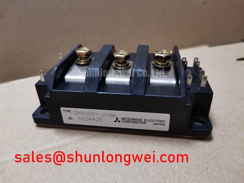
For engineers designing high-power industrial systems, the Mitsubishi QM150DY-2HBK IGBT module represents a benchmark in reliability and performance. This isn't just a component; it's a foundational building block for systems where uptime is non-negotiable and performance must be consistent under demanding load conditions. Its reputation is built on years of field-proven success in some of the most challenging power conversion applications.
- Robust Power Handling: With a solid 1200V collector-emitter voltage (Vces) and a 150A continuous collector current (Ic), it provides significant headroom for industrial-grade applications.
- Efficient Half-Bridge Topology: The dual IGBT (2-in-1) configuration simplifies inverter and chopper circuit design, reducing component count and simplifying PCB layout.
- Proven Reliability: Leveraging Mitsubishi's established chip technology, the QM150DY-2HBK is engineered for a long operational lifespan, minimizing maintenance cycles and total cost of ownership.
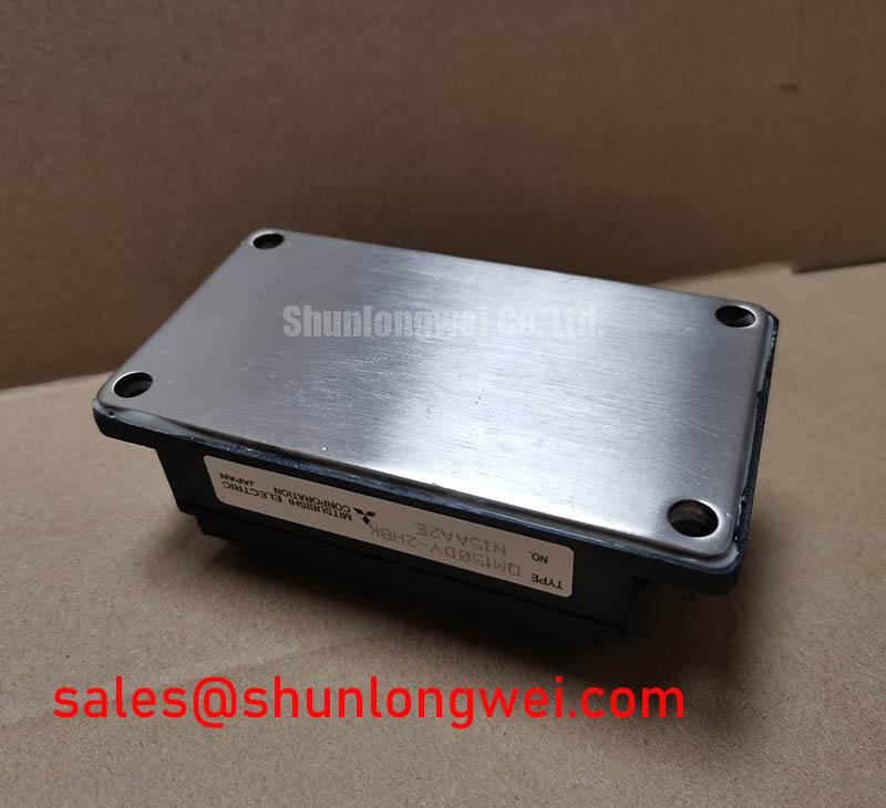
- Industry-Standard Footprint: Housed in a conventional package, this module serves as a seamless upgrade or direct replacement in existing designs, mitigating redesign risks and costs.
Key Technical Specifications
The following parameters highlight the core capabilities of the QM150DY-2HBK, providing a quick reference for design engineers. For a comprehensive breakdown of all electrical and thermal characteristics, download the official QM150DY-2HBK datasheet.
| Parameter | Value |
|---|---|
| Max. Collector-Emitter Voltage (VCES) | 1200 V |
| Max. Continuous Collector Current (IC) at TC=80°C | 150 A |
| Collector-Emitter Saturation Voltage (VCE(sat)) Typ. at IC=150A | 2.2 V |
| Max. Junction Temperature (Tj max) | 150 °C |
| Thermal Resistance, Junction to Case (Rth(j-c)) per IGBT | 0.16 °C/W |
Engineered for Demanding Industrial Applications
The true value of the Mitsubishi QM150DY-2HBK is realized in its application performance. Its design characteristics make it an optimal choice for several core industrial sectors:
- Variable Frequency Drives (VFDs): In motor control, the module's low VCE(sat) is critical for minimizing conduction losses, which are dominant in the lower switching frequencies typical of VFDs. Its robust thermal cycling capability ensures it can withstand the repetitive start/stop and variable load profiles of industrial motors.
- Uninterruptible Power Supplies (UPS): Reliability is paramount in UPS systems. The QM150DY-2HBK's rugged construction and proven die technology provide the high availability needed to protect critical loads, ensuring a stable power output during grid failures.
- Welding Power Supplies: Welding applications impose extreme electrical stress. This module's wide Safe Operating Area (SOA) and short-circuit withstand capability are essential for managing the high-current, low-impedance conditions inherent in arc welding processes, delivering both performance and durability. For more insights on how IGBTs are the linchpin of high-efficiency inverters, explore our detailed analysis.
A Deeper Look at the QM150DY-2HBK's Design Philosophy
The longevity and popularity of the QM150DY-2HBK stem from a deliberate engineering focus on balanced performance rather than chasing a single metric. The IGBT chip technology is optimized for a harmonious trade-off between conduction losses and switching losses. This makes it exceptionally efficient in applications operating in the 2 kHz to 15 kHz range, where many industrial systems reside. The design avoids the higher VCE(sat) often seen in ultra-fast switching devices, making it a more thermally efficient choice for these mainstream applications.
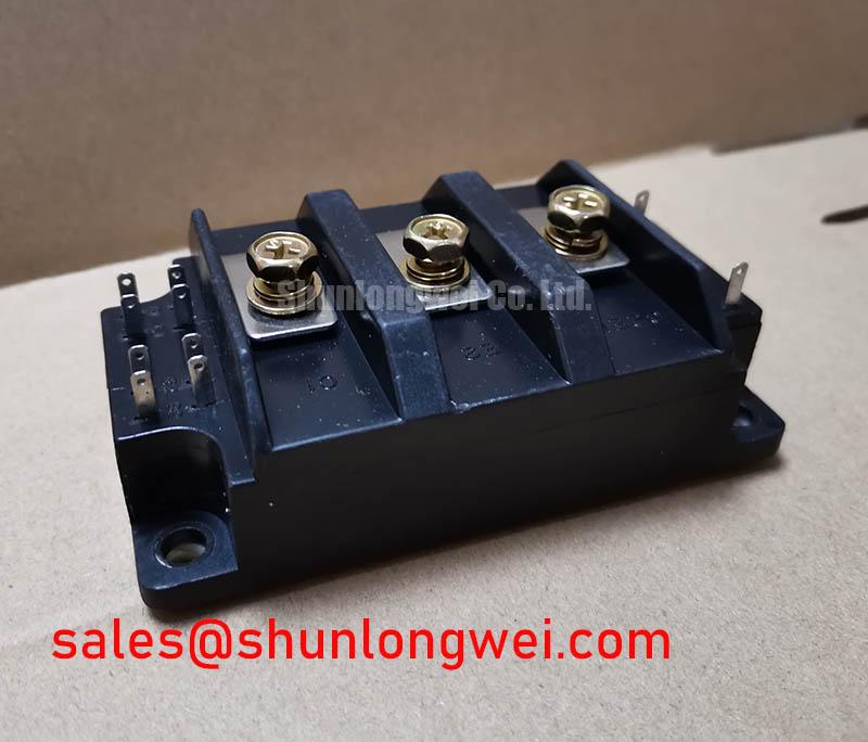
Furthermore, the module's thermomechanical structure is a testament to its industrial focus. The use of a high-quality ceramic isolation substrate and a substantial copper baseplate ensures a low thermal resistance path from the silicon to the heatsink. This superior thermal management is key to its high power cycling capability, enabling it to endure the thermal stresses of years of operation without succumbing to fatigue-related failures like bond wire lift-off or solder layer degradation.
Engineer's FAQ for the QM150DY-2HBK
- What are the best practices for the gate drive circuit?
A robust gate drive is critical. We recommend a drive voltage of +15V for turn-on and a negative voltage between -8V and -15V for turn-off. A negative turn-off voltage is crucial in this half-bridge module to provide a strong defense against dV/dt-induced parasitic turn-on, which can lead to shoot-through and catastrophic failure. For more practical advice, review these 5 tips for robust IGBT gate drive design. - Is this module suitable for new, high-frequency designs?
While the QM150DY-2HBK is highly versatile, its primary strength lies in applications with low-to-moderate switching frequencies (below 15 kHz). For new designs pushing higher frequencies, where switching losses become the dominant factor, you might consider newer generation IGBTs or SiC modules. For help with selection, please contact our technical team for a personalized consultation.