

Content last revised on October 17, 2026
QM75D1X-H Circuit Protection & Reliability: Calibrating Pollution Degree 3 Creepage Distances
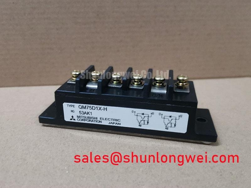
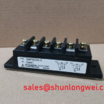
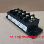
Isolate the equipment, discharge stored energy, and verify absence of hazardous voltage before disconnecting the QM75D1X-H from its drive wiring and power connections or assessing terminal condition, insulation surfaces, or mounting contact. For this Mitsubishi Electric power transistor, the supplied product specifications are 600 V, 75 A, and an Isolated Darlington Module package. Confirm the applicable rating conditions in the exact device documentation before using these figures as design limits. Keep that device identity central to the repair: a Darlington requires base-current control, rather than the insulated-gate drive associated with an IGBT. The distinction affects the driver checks and switching measurements needed before returning equipment to service. (onsemi switching-power-supply reference)
Inspect the insulating surfaces between the power terminals, mounting hardware, and grounded metalwork for dust deposits, moisture tracks, and contamination trapped beneath connection hardware. As a Design Consideration, pollution degree 3 describes an environment involving conductive pollution, or pollution that becomes conductive through expected condensation; it is not a certification automatically conferred by the module’s isolated package. Dust removal and condensation control therefore belong to the equipment maintenance plan, alongside the electrical inspection. ([infineon.com](https://www.infineon.com/assets/row/public/documents/24/42/infineon-applicationnote-mosfet-coolmos-electrical-safety-and-isolation-applicationnotes-en.pdf))
For an insulation-resistance assessment, the Engineering Recommendation is to isolate the module from connected electronics and follow the approved equipment procedure for terminal grouping, test voltage, duration, and discharge. Treat insulation resistance and dielectric withstand as different tests with different acceptance conditions. A high resistance reading does not establish the complete insulation rating, and an aggressive test voltage should not be selected simply because a tester offers it. Use the equipment’s insulation-coordination requirements to define the test, rather than borrowing conditions from another power module. (Infineon application and mounting guidance)
Measure creepage along the actual insulating surface, including the influence of bolts, washers, busbar edges, and nearby supports. Clearance is the shortest through-air separation and needs a separate assessment. Under the insulation-coordination principles described in IEC 60664-1, working voltage, pollution degree, insulating material characteristics, and the required insulation function affect the assessment. The module’s supplied 600 V electrical rating alone does not establish a universal terminal-spacing requirement. ([infineon.com](https://www.infineon.com/assets/row/public/documents/24/42/infineon-applicationnote-mosfet-coolmos-electrical-safety-and-isolation-applicationnotes-en.pdf))
As a Design Consideration, compare inspection findings before and after cleaning, while recording whether the cabinet was dry, recently cooled, or exposed to moisture. A repeatable change helps distinguish an environmental problem from a persistent insulation concern, but does not identify a particular internal failure mechanism. Keep the inspection focused on accessible surfaces and documented electrical acceptance criteria; no assumption about a proprietary ceramic substrate is needed to carry out this work. (Infineon electrical safety and isolation guidance)
For maintenance planning, use contamination found during scheduled shutdowns to adjust the inspection interval rather than assigning an unsupported calendar period to the module. Review enclosure condition and the route by which moisture or dust reaches the terminal area. When assessing abnormal operating conditions, the Field Engineer’s Handbook provides a related maintenance reference; acceptance limits still belong to the applicable device and equipment documentation. (Infineon electrical safety and isolation guidance)
Transient Dynamics & Electrical Design: Transient Thermal Impedance on QM75D1X-H
Capture the load pulse duration, repetition pattern, and case-temperature history before estimating junction heating. As an Engineering Calculation, a single rectangular power pulse starting from thermal equilibrium under an approximately constant case-temperature boundary gives a junction-temperature rise equal to pulse dissipation multiplied by the applicable junction-to-case transient thermal impedance at that pulse duration. Repeated pulses require the remaining heat from earlier pulses to be included; a steady-state thermal-resistance value cannot reproduce that history by itself. ([onsemi.com](https://www.onsemi.com/download/data-sheet/pdf/mjh16006a-d.pdf))
A multi-RC thermal model is useful when its response represents the device’s documented transient thermal behavior. As a Design Consideration, apply the measured loss waveform to that model and evaluate the resulting temperature excursion against the applicable junction-temperature limit. Keep the thermal boundary consistent: a junction-to-case model does not automatically include an aging interface layer, a restricted heatsink, or changing cabinet airflow. Those external conditions need their own representation in the thermal assessment. (Infineon thermal equivalent circuit guidance)
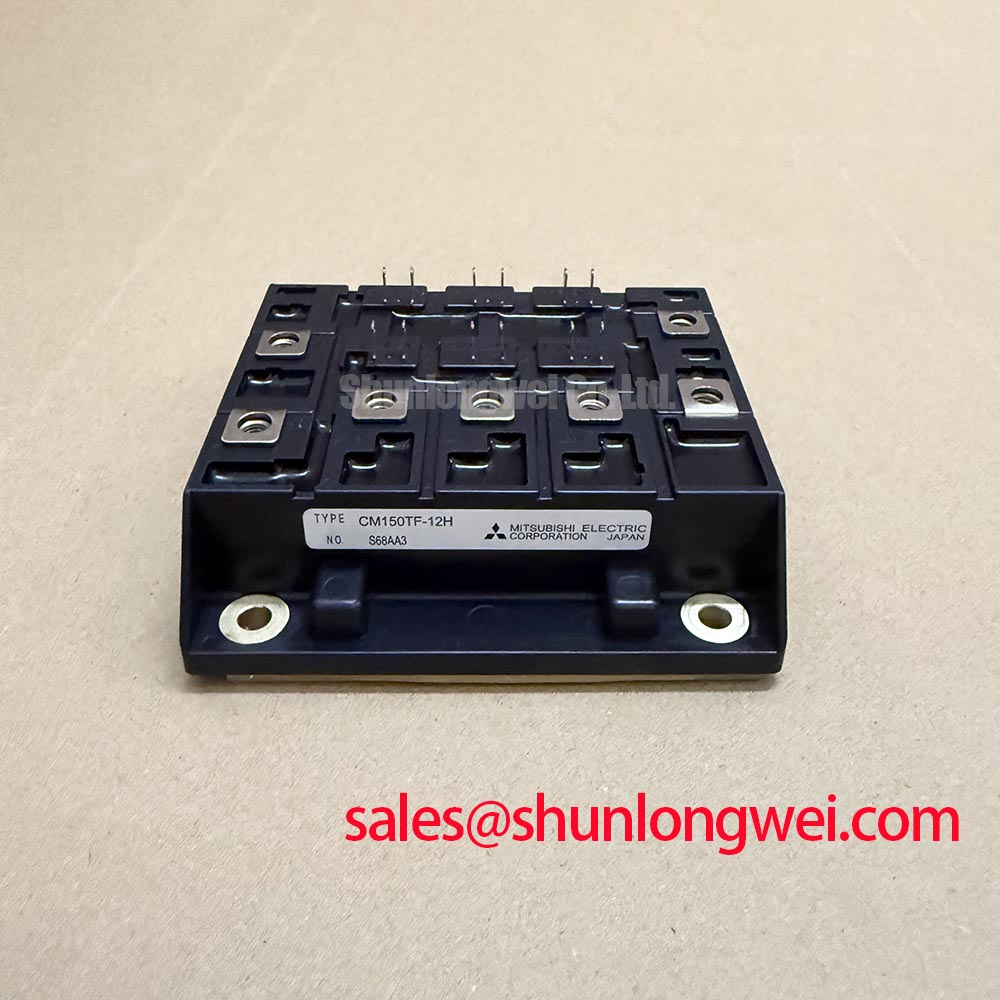
Before considering a different module, compare the electrical class and the integration details separately. The table distinguishes the supplied QM75D1X-H specifications from information that needs a model-specific datasheet check. The linked QM150DX-H is a same-manufacturer comparison candidate, not an approved replacement: its higher current rating does not establish matching terminals, drive requirements, or switching behavior. The linked comparison document distinguishes a 450 V collector-emitter sustaining rating from its 600 V rating with reverse base-emitter bias; these are not interchangeable operating limits. ([slw-ele.com](https://www.slw-ele.com/datasheets/QM150DX-H.pdf))
| Comparison Item | QM75D1X-H | QM150DX-H |
|---|---|---|
| Manufacturer | Mitsubishi Electric | Mitsubishi Electric |
| Voltage rating | 600 V — supplied specification; verify rating definition and conditions | 600 V VCEV; 450 V VCEO(SUS); VCEV(SUS) is 600 V at VBE = −2 V, per the linked comparison document |
| Collector current rating | 75 A — supplied specification; verify applicable conditions | 150 A continuous collector-current maximum rating; rating table specifies Tj = 25°C unless otherwise stated, not a recommended operating current |
| Product category | Isolated Darlington Module | Split-dual Darlington transistor module |
| Terminal map, dimensions, and base drive | Consult Datasheet | Compare against the existing assembly |
| Insulation-test conditions, transient thermal data, fault withstand, and tightening torque | Consult Datasheet | Use model-specific limits; do not transfer them to QM75D1X-H |
For parallel operation, the Engineering Recommendation is to assess each branch’s current, base drive, connection resistance, and thermal condition. Symmetrical busbars reduce one source of imbalance, but do not establish equal sharing by themselves. Do not assume a beneficial positive temperature coefficient of collector-emitter saturation voltage without the relevant characteristic curves. System-level droop control concerns coordination between controlled sources; it does not replace device-level current-sharing verification. (Danfoss power-module application guidance)
Industrial inverter welders and medium-frequency induction-heating power supplies are potential compatibility-assessment examples, subject to the original switching topology and base-drive requirements. When reviewing the surrounding conversion chain, identify the actual role of associated components such as the 6DI75A-050 from their circuit diagrams, rather than treating a power transistor module as an interchangeable front-end rectifier. This is a Design Consideration, not an application approval for either part. (onsemi switching-power-supply reference)
Benchtop Waveform Tuning: Mitigating Stress via Fault-Clearing Dynamics: Type-I/II Short-Circuit Scenarios on QM75D1X-H
Record collector current, collector-emitter voltage, and base-current behavior together when investigating a protection trip. As a Design Consideration, the useful question is whether detection and turn-off keep the Darlington’s operating trajectory within its applicable safe operating area. Bipolar transistor protection must account for stored charge and secondary breakdown, not simply copy the timing or gate-drive settings of a modern IGBT protection circuit. (onsemi switching-power-supply reference)
Type-I and Type-II short-circuit descriptions distinguish switching into an existing fault from a fault developing during conduction. They do not establish a QM75D1X-H short-circuit withstand time. Mitsubishi’s cited IGBT application guidance treats short-circuit capability as conditional on the individual device and test circuit; it does not specify the capability of this Darlington module. The Engineering Recommendation is therefore to establish the complete detection-to-current-interruption sequence under controlled, energy-limited conditions within the device’s documented safe operating area, including sensor delay, logic response, driver behavior, and the final current decay. ([mitsubishielectric.com](https://www.mitsubishielectric.com/semiconductors/powerdevices/application_notes/powermos4_0.pdf))
A staged turn-off strategy needs particular care with a Darlington. Reducing the interruption rate can suppress inductive overshoot, but extending simultaneous collector voltage and current can increase device stress. As a Design Consideration, tune the base-charge extraction and any clamping network together, using the actual reverse-bias safe operating area as the boundary. The manufacturer’s Mitsubishi Electric Power Semiconductors & High-Power Modules resources provide the appropriate starting point for device-family technical guidance. (onsemi bipolar-transistor safe-operating-area reference)
Check the existing MOV and snubber network as coordinated parts of the protection circuit. The Engineering Recommendation is to assess continuous-voltage suitability, clamping behavior at the relevant surge current, pulse-energy duty, and connection layout. A varistor’s nominal marking is not the voltage that appears across the transistor during every transient. Compare the observed collector-voltage peak with the protection component’s characteristics and the device’s applicable operating limits before changing the network. (Littelfuse varistor design notes)
Keep insulated-gate terminology out of the base-drive diagnosis: reverse-transfer capacitance is not a charge quantity, and a MOSFET-style Miller plateau is not a substitute for measuring Darlington base current and storage behavior. Where active clamping is considered, evaluate the resulting transistor dissipation and turn-off trajectory, rather than treating the clamp as an unrestricted energy absorber. These are Design Considerations for the surrounding circuit, not additional QM75D1X-H specifications. (onsemi switching-power-supply reference)
Inspect the freewheeling path during commutation as well. Abrupt diode recovery can excite overshoot and ringing, so the Engineering Recommendation is to compare recovery current and voltage under representative load conditions. Do not assign this module an unsupported recovery-softness factor or surge-current limit. Recovery behavior can affect switching stress and electromagnetic emissions, but it does not establish equipment-level EMC compliance. (onsemi rectifier reference)
QM75D1X-H Circuit Protection & Reliability: Preventing Terminal Overheating via Periodic Inspection
Measure a suspect bolted connection with a four-terminal micro-ohmmeter during an isolated shutdown, placing the voltage-sensing contacts across the joint being assessed. As an Engineering Recommendation, exclude unintended parallel paths and preserve the probe positions in the maintenance record. Four-wire measurement reduces the influence of test-lead resistance; repeatability still depends on the connection geometry and test conditions. Judge the result against the approved assembly baseline rather than an invented universal micro-ohm threshold. (Megger low-resistance measurement guidance)
Correlate resistance trends with thermal images taken under comparable operating conditions. A hot connection warrants investigation, but the image alone does not establish whether the cause is joint resistance, unequal current, or surrounding heat. As a Design Consideration, record load, viewing position, ambient conditions, and the camera’s emissivity settings so that successive inspections remain meaningful. Reflective terminal surfaces can complicate temperature interpretation. (FLIR electrical inspection guidance)
During a planned shutdown, inspect busbar alignment, terminal seating, and the condition of the fastening hardware before applying the documented tightening procedure. More torque is not automatically better: overtightening can distort a joint and increase resistance. The Engineering Recommendation is to use calibrated tooling and the correct assembly-specific torque, then repeat the electrical check after corrective work. Do not transfer a mounting-screw torque to an electrical terminal simply because the fasteners appear similar. (Megger low-resistance testing guidance)
Keep heatsink cleaning and thermal-interface inspection linked to the same maintenance history. When removal is justified, assess interface coverage and surface condition, then restore the approved thermal material and mounting sequence. As a Design Consideration, paste thickness and tightening procedure belong to the particular assembly; an arbitrary extra layer is not a remedy for poor contact. (Danfoss power-module mounting guidance)
Maintenance Note: Trend terminal temperature alongside load and airflow, and investigate a repeatable rise before returning the assembly to unrestricted duty. (FLIR electrical inspection guidance)