
Content last revised on September 20, 2026
RM400HA-24S Thermal-Electrical Optimization: Dynamic Firing Delay Angle Adjustment under Practical Tuning
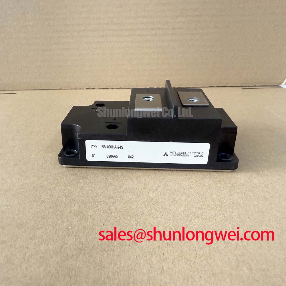
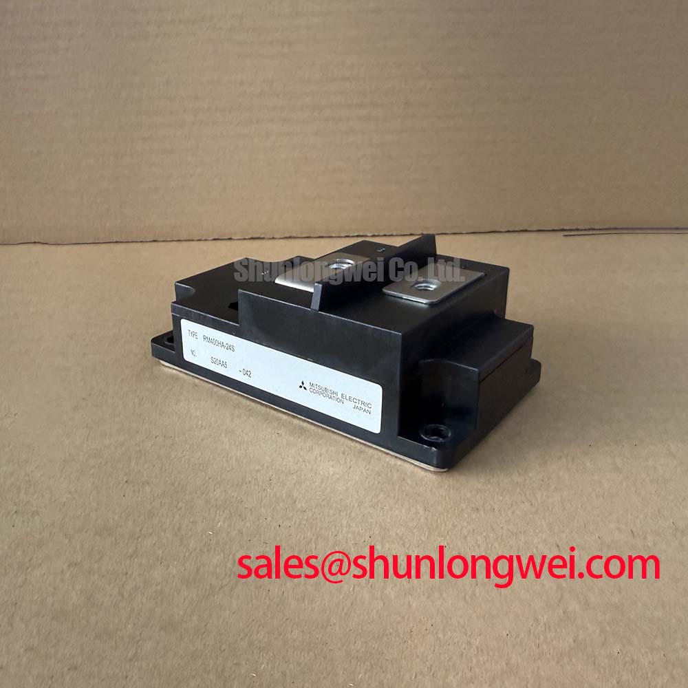
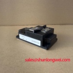
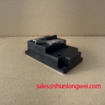
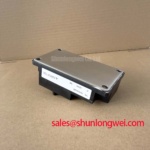
Before reconnecting a removed unit, isolate the cabinet, inspect the module body and terminals for cracking, discoloration, looseness, or damaged insulation, then compare the nameplate rating with the original circuit documentation. The RM400HA-24S is a Mitsubishi Electric Diode Module rated at 1200V and 400A as an Official Datasheet Specification. Its electrical role must be verified from the installed schematic before a repair decision is made.
In a grid connected static var compensator or thyristor switched capacitor assembly, firing angle adjustment belongs to the thyristor control path, while a diode module can serve within associated rectification, freewheeling, or auxiliary power paths according to the equipment topology. A firing angle sweep from zero through delayed conduction changes the rectifier’s average output and its reactive power demand. The maintenance task is to confirm that the RM400HA-24S remains in the correct diode position and is not being evaluated as a gate controlled switching device.
For practical tuning, review phase voltage waveforms, current balance, and the controller’s firing reference against the original commissioning records. Delayed firing can alter waveform distortion and power factor, but neither a gate pulse nor a gate delay specification applies to this diode module. The system integrator should verify terminal identification, creepage clearance, and the permitted voltage stress from the original equipment documentation.
⚠️ Field Alert: Tighten power terminals and heatsink fasteners only to the equipment or module documentation requirement, using an even sequence so mechanical stress does not distort the module base.
A useful repair comparison may include the RM500CZ-M, but electrical function, terminal layout, cooling interface, control requirements, and all ratings must be checked against the existing circuit before any substitution is considered.
Transient Dynamics & Electrical Design: Fuse Total Clearing I2t versus Device Melt on RM400HA-24S
A dead short investigation should begin with evidence from the failed fuse, busbar condition, capacitor bank, and diode module terminals rather than assuming a single fault origin. The RM400HA-24S has an Official Specification rating of 1200V and 400A; these ratings do not by themselves provide a published fuse coordination value or a total clearing I²t limit for a specific installation.
Fuse selection is therefore a Design Consideration. The protection engineer should compare the semiconductor fuse manufacturer’s pre arcing and total clearing I²t data with the protected circuit’s documented withstand capability, prospective fault current, conductor arrangement, and upstream protection coordination. The aim is to interrupt fault energy before mechanical damage propagates through conductors, capacitors, or semiconductor connections. A fuse catalogue value cannot be transferred between systems without checking the actual fault loop and operating voltage.
Inspect busbar surfaces for uneven contact marks and confirm that the original conductor stack order is retained. Loose or oxidized joints can add resistance and heat, while poor busbar geometry can increase inductive stress during current interruption. Keep the high current path compact where the equipment layout permits, then verify voltage peaks and current interruption behavior through system level testing.
In SVC auxiliary power sections, engineers may also inspect related rectifier positions such as the RM100HA-20F. This is a topology review step, not evidence that the two modules share the same electrical role or are interchangeable.
Assembly Integrity & Layout Architecture: Implementing Gate Trigger Current Temperature Dependence for RM400HA-24S
The RM400HA-24S is specified as a diode module, so it has no gate trigger current, gate pulse rise time, holding current, or multipulse firing requirement. Those parameters belong to thyristor and other controlled semiconductor positions in a static var compensator. Treating this module as a gate controlled device can lead to incorrect wiring checks and an incomplete fault assessment.
During onsite diagnosis, separate the diode module checks from the firing board checks. With the system safely isolated and stored energy discharged under site procedure, use a meter to compare the forward and reverse behavior of the installed diode path with the circuit schematic and, where available, a known good assembly. An unexpected reading may arise from parallel components, snubber networks, transformer windings, or measurement lead placement; disconnect only as far as the documented service procedure requires before drawing conclusions.
Control loop instability can also change how thyristor driven equipment behaves during capacitor switching. The relationship between feedback response and loop gain is usefully described in this transfer function reference. This is an Engineering Recommendation for controller analysis and does not establish a module parameter. Where solid state switching functions are present, technicians can also review the general operating context described by solid state relay principles.
RM400HA-24S Thermal-Electrical Optimization: Junction-to-Heatsink Heat Dissipation in Practical Tuning
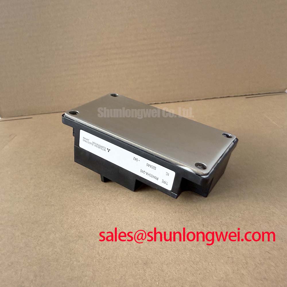
Remove old interface residue from both the heatsink and module base before installation, then inspect the heatsink surface for burrs, corrosion, scratches, or local flatness issues. Apply thermal interface material as a controlled, even layer according to the original equipment service instruction. The objective is full thermal contact without trapped debris, dry areas, or excessive compound that prevents stable seating.
No junction to case thermal resistance, baseplate construction, mounting torque, or permissible thermal interface thickness is provided in the available Official Specification data for this product page. These values must not be assumed. Heat dissipation planning is a Design Consideration based on measured current waveform, conduction losses, cabinet airflow, heatsink performance, ambient condition, and the original Mitsubishi Electric documentation.
After assembly, examine terminal alignment before final tightening. Busbars should reach the module terminals without forced bending or side load. During controlled commissioning, compare temperature distribution across the module and adjacent connections using the site approved method. A localized rise may indicate contact quality, current sharing, airflow, or circuit loading issues and should be investigated against the complete power path.
For broader guidance on evaluating semiconductor devices, protection boundaries, and system reliability test planning, consult the Power Electronics Masterclass. Its concepts should be applied with the RM400HA-24S’s confirmed diode function and the host equipment’s documented operating limits.