Content last revised on September 19, 2026
Preventing Spurious Faults: AC Input Transient Overvoltage Clamping Guidelines for SKD82/04
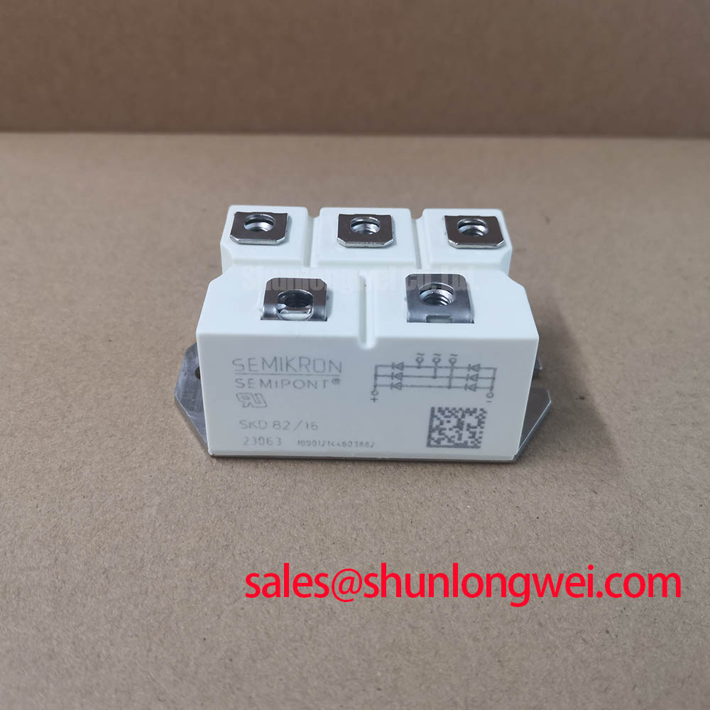
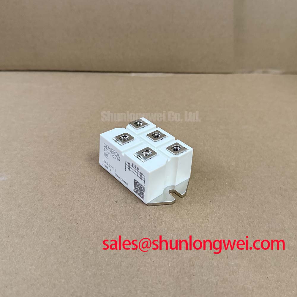
With the power isolated and the DC link discharged, verify the module marking, inspect the Semipont housing for cracking or terminal distortion, and confirm that the replacement position is bounded by the supplied 400.0 V voltage rating and 82.0 A current rating. The SKD82/04 is a Semikron bridge rectifier module in the Semipont package. These official specifications define the electrical identity to be checked before a maintenance team reconnects AC input conductors or recommissions a rectifier cabinet.
| Parameter | Value | Classification |
|---|---|---|
| Product model | SKD82/04 | Official identification |
| Manufacturer | Semikron | Official identification |
| Voltage rating | 400.0 V | Official specification |
| Current rating | 82.0 A | Official specification |
| Package | Semipont | Official specification |
| Product category | Bridge rectifier module | Product classification |
For a high current green hydrogen electrolyzer DC power rectifier, this module should be evaluated as part of the complete AC to DC conversion assembly. The rectifier transformer, upstream protective devices, busbar geometry, cooling arrangement, control interlocks, and electrolyte process load all determine the stresses actually seen by the bridge. The stated module ratings do not replace verification of those system conditions.
Begin at the AC input terminals and trace the protection path toward the bridge rather than treating nuisance trips as a module only issue. Contactors, transformer leakage inductance, utility disturbances, and nearby switched loads can produce transient conditions that reach the rectifier assembly. The 400.0 V rating is an official specification for SKD82/04, so recorded operating and transient voltages must be assessed against the equipment designer’s approved voltage envelope rather than against a presumed margin.
IEC 61000 4 5 is commonly used at system level when evaluating surge immunity. A bridge rectifier module does not independently establish cabinet level compliance with that standard. As a Design Consideration, inspection should establish whether the original equipment uses coordinated surge protection, such as metal oxide varistors at the incoming AC side and an RC network where the converter topology requires damping. Selection of those parts depends on the measured supply arrangement, transformer behavior, protective coordination, and the voltage waveform at the module terminals.
Do not select a replacement fuse from nominal module current alone. Fuse coordination depends on the manufacturer’s time current characteristics, prospective fault current, conductor capability, and the available I²t information for both fuse and semiconductor. No fuse I²t rating is provided here as an official specification for SKD82/04. Maintenance personnel should retain the original approved fuse class where possible and obtain the rectifier documentation before changing protective-device ratings.
Terminal joints deserve the same attention as surge clamps. A discolored lug, relaxed fastener, or contaminated busbar surface can add resistance and create local heating that is easily mistaken for rectifier degradation. Clean only according to the equipment maintenance procedure, align the terminal hardware without imposing side load on the package, and use the documented tightening method for the installed hardware. Mounting and terminal torque values are not stated as official SKD82/04 data in the supplied information, so the original equipment manual and applicable Semikron mechanical documentation remain the controlling references.
When a maintenance review requires a smaller related bridge for comparison, the SKD 25/14 can be reviewed as a separate part number. Its suitability must be determined from its own ratings, package details, circuit conditions, and thermal design; a shared product family name does not establish direct interchangeability.
Field Diagnostics & Commissioning: Baseplate Thermal Resistance in SKD82/04 Topologies
Before applying full load, examine the heat transfer path from the Semipont package to the heatsink. Uneven contact marks, hardened thermal compound, trapped debris, warped mounting faces, or an obstructed airflow route can prevent a uniform thermal interface. Thermal resistance across a completed assembly is influenced by the module, mounting surface, interface material, clamp force, heatsink condition, airflow, and ambient environment. A calculated or measured assembly value must therefore be treated as an Engineering Calculation or test result, not as an official SKD82/04 junction to case specification unless it comes directly from the applicable manufacturer datasheet.
Use a controlled commissioning sequence. First inspect the cold mechanical installation. Then operate at the approved reduced commissioning condition while monitoring the available cabinet temperature points, AC balance, DC output stability, and cooling response. A temperature difference between parallel paths may indicate unequal loading, a poor interface, restricted airflow, or an upstream connection issue. It does not identify one cause by itself. Compare observations with a known good channel or the original equipment acceptance baseline when available.
In rectifier cabinets that have been idle in cold or humid conditions, check for moisture, condensation traces, blocked filters, and corrosion around terminals before energization. These are maintenance conditions external to the module but can influence leakage paths and connection resistance in the assembly. ⚠️ Maintenance Note: Monitor contact temperature rise during normal production duty and verify that the cooling air path remains clear at each scheduled service interval.
Thermal paste should be applied by the equipment manufacturer’s specified process, with attention to continuous coverage and avoidance of excess material at electrical connection areas. Design Consideration: distribute mechanical pressure evenly to support stable heat transfer without distorting the package. If thermal anomalies persist after cleaning and mechanical inspection, capture current and temperature trends during the actual load cycle rather than relying on a brief no load test.
The power semiconductor product range described by the Semikron Danfoss Power Electronics & Modules Official Hub provides useful manufacturer context for module based power conversion. For the installed SKD82/04 assembly, the original converter documentation remains essential because it defines the heatsink, airflow, conductor layout, and protective coordination actually used in service.
Field Diagnostics & Commissioning: Dynamic Firing Delay Angle Adjustment in SKD82/04 Topologies
SKD82/04 is classified here as a bridge rectifier module, so it should not be assigned a gate firing function that belongs to separate controlled devices. In systems where an upstream phase controlled stage adjusts firing delay angle across an approximate range from zero degrees to 150 degrees, the bridge can still experience a changing input waveform and changing thermal duty. The control board, its synchronisation circuit, and the associated controlled rectifier devices determine firing delay behavior, while SKD82/04 must be assessed within the resulting electrical conditions.
During commissioning, verify the phase reference, transformer secondary waveform, DC output ripple, and current balance before adjusting any control setpoint. A delayed firing angle generally changes the conversion transfer characteristic and can increase reactive power demand and harmonic content. The actual effects depend on source impedance, transformer design, smoothing inductance, load dynamics, and the control strategy. Engineering Recommendation: use isolated measurement equipment and compare captured waveforms against the approved system commissioning record.
A high current green hydrogen electrolyzer DC power rectifier may have process controls that respond to DC voltage, current, temperature, or interlock states. Do not bypass those controls to force a rectifier test. Instead, use the equipment supplier’s service mode and confirm that each phase input and DC output follows the authorised sequence. If output instability appears while the bridge remains electrically intact, inspect the phase control signal path, supply balance, sensor feedback, and DC bus connections before attributing the condition to the rectifier module.
For systems using a different voltage class within the same general product naming structure, SKD82/18 is a separate component reference that can be examined alongside the original circuit requirements. Voltage rating, package arrangement, terminal layout, and electrical operating conditions must all be verified before any engineering decision is made.
Where a maintenance team is assessing transient margins during controlled rectifier operation, the practical reference is the measured voltage at the bridge terminals during the relevant switching and commutation events. The application material in The Ultimate IGBT Knowledge Base can support broader power semiconductor troubleshooting principles, while the approved equipment schematic governs this bridge rectifier installation.
Field Diagnostics & Commissioning: High Frequency Switching Loss Dissipation in SKD82/04 Topologies
In a line frequency rectifier, commutation behavior can still create current and voltage transitions that are important during diagnosis, particularly where transformer inductance, capacitive filtering, or nearby switched converters affect the waveform. Reverse recovery peak current and recovery time are not provided as official specifications in the supplied SKD82/04 information. They should not be assigned assumed values for loss calculations, snubber selection, or electromagnetic compatibility claims.
Use an oscilloscope and appropriately rated probes to observe the AC terminal waveform, DC bus response, and any ringing that occurs during normal commutation. Ringing may be associated with layout inductance, the transformer and filter network, external suppression components, measurement technique, or an abnormal connection. Design Consideration: minimise unintended loop inductance where it contributes to commutation overshoot, then verify peak voltage margins against the measured DC link and terminal waveform under the actual operating condition.
Where an electrolyzer power supply also contains high frequency auxiliary converters, keep their switching current paths and sensing circuits organised according to the original cabinet design. A bridge module should not be blamed for noise that originates in a separate converter stage, shield termination issue, or control supply disturbance. Review grounding continuity, cable routing, filter condition, and the location of voltage sensing leads before modifying suppression hardware.
The Semikron MiniSKiiP® Power Modules information illustrates that power module families have application specific mechanical and electrical characteristics. SKD82/04 must be maintained according to its own 400.0 V, 82.0 A, and Semipont identification, with waveform and thermal checks performed in the complete rectifier system.