

Content last revised on September 18, 2026
Transient Dynamics & Electrical Design: Baseplate Thermal Resistance on SKDH100/14
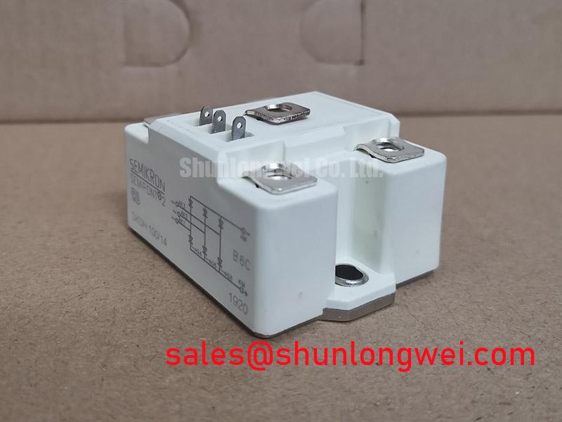
Before connecting the module to a test fixture, isolate the assembly, identify the DC and AC terminals from the original equipment documentation, and record cold-state diode-mode readings for every permitted rectification path. The SKDH100/14 is a Semikron bridge rectifier module in the Semipont housing, with an official repetitive voltage rating of 1400 V and a specified current rating of 100 A. These ratings define the electrical identity that should be matched during repair assessment; they do not by themselves establish suitability for a particular bus voltage, overload profile, heatsink, fuse, or enclosure.
For incoming inspection, compare the measured forward paths against each other rather than relying on an invented universal diode-drop threshold. A substantial inconsistency between otherwise equivalent paths can justify further investigation, but test-lead polarity, contact oxidation, parallel circuit paths, and temperature can all affect the reading. The reverse-direction check should be performed with the module disconnected from the surrounding circuit where practical. The test verifies basic terminal behavior; it does not replace an insulation test, a controlled load test, or an in-circuit waveform review.
| Item | Value | Classification |
|---|---|---|
| Manufacturer | Semikron | Official product identification |
| Module type | Bridge rectifier module | Official product identification |
| Rated voltage | 1400 V | Official Specification |
| Rated current | 100 A | Official Specification |
| Housing | Semipont | Official Specification |
The supplied official information does not state junction-to-case thermal resistance, baseplate flatness, permissible mounting torque, terminal torque, fuse I²t coordination, or an approved thermal-interface material. Those values must be verified from the exact Semikron documentation and the equipment bill of materials before a replacement module is mounted. A bridge rectifier can be electrically correct on the bench yet run outside its intended thermal condition when the heatsink face is contaminated, distorted, or incorrectly clamped.
As a Design Consideration, inspect the heatsink contact area for burrs, hardened compound, corrosion, and local raised areas. Apply thermal material only according to the verified module and system assembly requirements, then tighten hardware in a balanced sequence so contact pressure is not concentrated at one edge. The installer should confirm mounting and terminal fastener requirements from the applicable mechanical drawing rather than applying a generic torque figure to this Semipont package.
Bench Tip: De-energize and discharge the DC link before moving test leads or mounting hardware, then retain the cold-state readings as the comparison baseline after commissioning.
In grid-tied static var compensator and thyristor-switched capacitor equipment, a rectifier module can be evaluated for an auxiliary or associated conversion function only after the rectified voltage, current waveform, fault-energy path, and cooling arrangement have been checked against the 1400 V and 100 A specified ratings. That is an integration assessment, not a claim that the module is assigned to every SVC topology. Semikron’s power semiconductor portfolio provides useful manufacturer context, while the exact module documentation remains the controlling reference for installation limits.
Preventing Spurious Faults: Dynamic Voltage Sharing and RC Damping in Guidelines for SKDH100/14
The first circuit review should distinguish the rectifier bridge from the controlled switching devices around it. SKDH100/14 is specified as a bridge rectifier module, so gate-triggered behavior, turn-on dv/dt immunity, and gate-drive timing are not attributes that should be assigned to this module without evidence. In an SVC or thyristor-switched capacitor cabinet, those concerns can belong to separate thyristors, contactors, switching assemblies, transformers, or control circuits. Keeping that boundary clear prevents a repair team from applying a gate-drive diagnosis to an uncontrolled diode bridge.
RC damping and series reactor selection are system-level Design Considerations. They can influence ringing and commutation stress where transformer leakage inductance, capacitor-bank connections, busbar geometry, cable routing, and other switching devices form a resonant path. Their component values cannot be derived from the official 1400 V, 100 A, and Semipont identification alone. Designers should capture voltage and current waveforms at the relevant circuit nodes, identify the event that needs damping, and verify peak voltage margins against the DC-link and device limits during controlled switching tests.
For rectifier service, the relevant question is often whether recovery current, wiring inductance, and source impedance create a transient at the bridge that the installation has not accounted for. An oscilloscope measurement taken with an appropriate high-voltage differential probe and a current measurement suited to the expected waveform can reveal ringing, imbalance, or an abnormal commutation event. A waveform that differs from a known-good channel may indicate a wiring, source, capacitor, snubber, or semiconductor issue; it should not be treated as proof of a single cause without isolating the circuit.
Fuse coordination also needs the actual fuse data and the protected circuit’s prospective fault current. The official product information supplied for SKDH100/14 does not provide an I²t table. A fuse chosen only by nominal current can be unsuitable because semiconductor protection depends on the interaction among the fuse’s clearing characteristic, available energy, line impedance, and the fault location. The system engineer should review the rectifier branch with the fuse manufacturer’s curves and the original protection design.
When the service task calls for a comparison unit, SKD82/18 can be reviewed as a separate Semikron-family module. It should not be treated as an automatic substitute: voltage class, current capability, circuit configuration, terminals, mechanical footprint, thermal requirements, and protection coordination all require direct verification. In a broader input or auxiliary rectification chain, the SKD 25/14 is another module that may be relevant to a documented topology, subject to the same pinout and ratings review.
Field Diagnostics & Commissioning: Pulse-Transformer Isolated Firing Circuit in SKDH100/14 Topologies
During commissioning, trace the pulse-transformer isolated firing circuit to the actual controlled semiconductor before interpreting its pulse shape. The SKDH100/14 bridge rectifier has no gate terminal identified by the supplied official specifications, so firing-pulse rise time, holding-current support, and multi-pulse gate strategies are not module parameters for this bridge. They may be critical elsewhere in a thyristor-switched capacitor panel, but they must be checked against the specifications of the actual thyristor and the documented firing circuit.
A practical diagnostic sequence begins with the complete cabinet isolated and discharged. Confirm that the bridge terminals agree with the equipment schematic, inspect connectors and busbar joints for heat evidence or movement, and make cold diode-mode comparisons with external parallel paths removed where feasible. Next, review control pulses at the isolated driver output and at the intended controlled-device connection using the test method required by the equipment design. This sequence separates rectifier-path verification from firing-path verification and reduces the chance that unrelated controls are blamed for a bridge fault.
The requested condition of a gate-current slew rate greater than 1 A per microsecond is not an official specification supplied for SKDH100/14, and it should not be imposed as a requirement on this module. For a separately specified thyristor firing circuit, the relevant pulse current, rise behavior, pulse duration, repetition strategy, isolation capability, and resistor network must be obtained from the controlled device documentation and validated in the finished assembly. Engineering Recommendation: assess those signals while observing the corresponding main-current and line-voltage behavior, because a clean bench pulse may not represent the installed system under noise and load.
Where a rectifier bridge is adjacent to capacitor switching equipment, an unexpected DC-side waveform can result from more than one condition. Possible contributors include phase loss, a poor terminal connection, source imbalance, an open or shorted rectification path, a changed capacitor-bank condition, or an issue in the switching command chain. Compare all line-to-line conditions, DC ripple behavior, and equivalent phase paths against the approved schematic and a known-good section where available. This produces traceable evidence for a repair decision without claiming a one-to-one symptom diagnosis.
For background on modular power conversion considerations, the engineering discussion in The Race for Efficiency can help frame why physical layout, current paths, and thermal interfaces deserve attention. Its subject matter does not replace the verified electrical and mechanical requirements for this particular bridge rectifier or for an SVC installation.
Benchtop Waveform Tuning: Mitigating Stress via High-Frequency Switching Loss Dissipation on SKDH100/14
For a benchtop evaluation of SKDH100/14, begin by confirming that the fixture applies a rectifier-appropriate source and load condition and that the wiring follows the documented terminal arrangement. Record AC-side and DC-side waveforms before changing any damping or layout variable. The module’s official 1400 V voltage rating and 100 A current rating are the available factory rating data; the supplied data does not state reverse-recovery peak current, recovery time, switching-energy curves, maximum switching frequency, or soft-recovery classification.
Because those dynamic values are not supplied, it would be inaccurate to quote an Irrm or trr figure, or to prescribe a high-frequency operating point for this specific module. Diode reverse recovery is still a useful system-level Design Consideration when the bridge commutates with inductive source paths or interacts with nearby switched stages. The team should measure the actual commutation current and voltage at the installed operating condition, then judge whether ringing, peak stress, thermal rise, or conducted noise calls for a documented system change.
Loop inductance should be minimized where it contributes to turn-off overshoot, with final peak margins verified against the DC-link voltage during switching tests. This is a principle, not a module-specific layout dimension. Short, mechanically secure current paths and clean heatsink contact can improve repeatability, but the final layout depends on the cabinet’s busbar arrangement, source transformer, capacitor-bank structure, protection devices, and service access requirements.
High-frequency switching loss is often discussed around IGBTs and controlled switches. The SKDH100/14 should instead be treated as the bridge rectifier defined by its official specifications unless the exact manufacturer document states additional dynamic characteristics. In mixed converter equipment, test the bridge separately from any regenerative braking chopper, battery bidirectional DC-DC stage, or thyristor gate circuit. Those functions have their own switching devices and control constraints, and assigning their losses or dead-time requirements to the rectifier bridge would obscure the real fault boundary.
After any approved adjustment, repeat cold diode checks, controlled no-load verification, and the relevant loaded waveform capture. Compare terminal temperatures and electrical symmetry across equivalent paths using the system’s accepted procedure. This disciplined record makes it possible to determine whether the Semipont bridge is behaving consistently with the installation, while preserving the distinction between official module ratings and system-determined operating results.