



Content last revised on October 4, 2026
SKET400-16E Operational Boundaries: Evaluating Fault Clearing
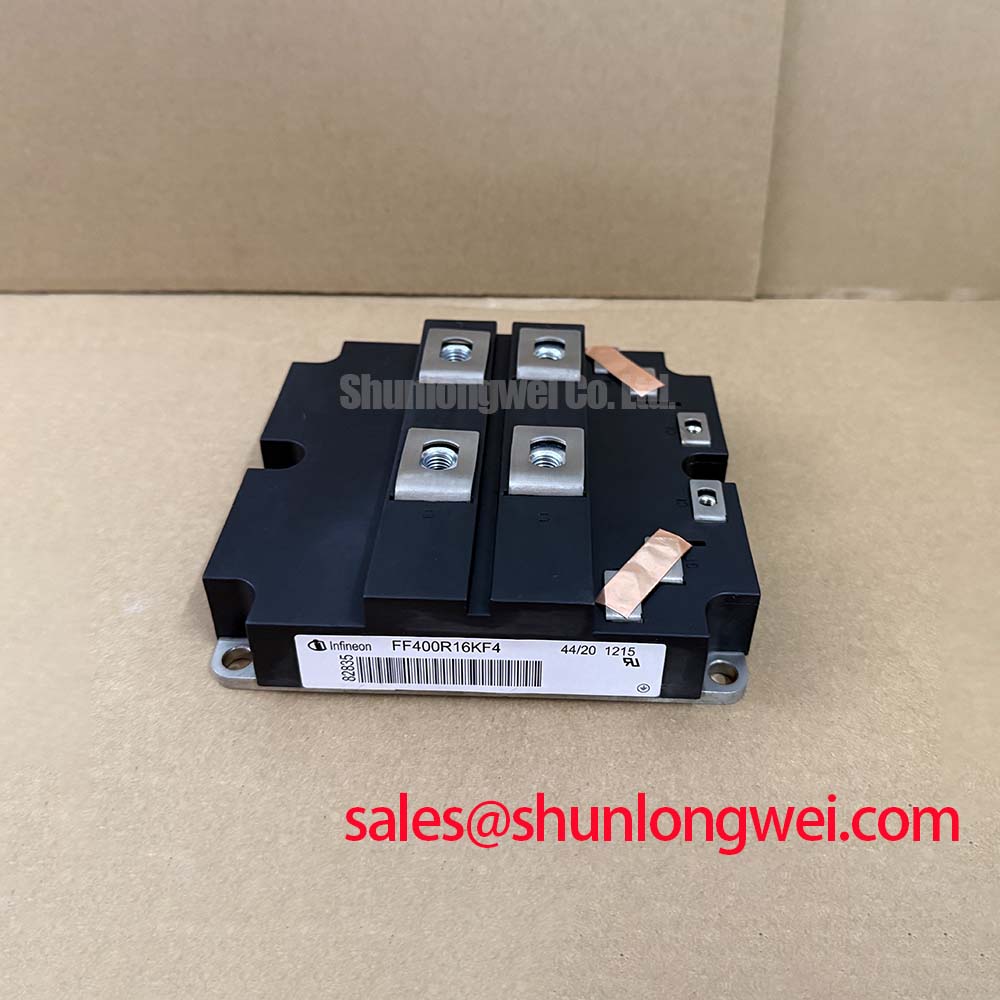
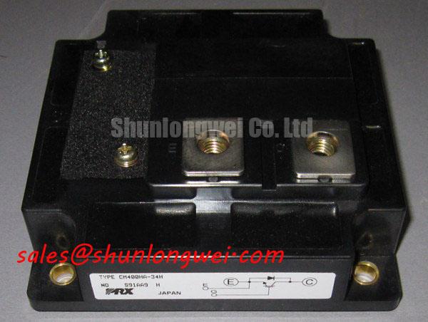
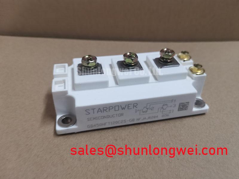
With the equipment isolated and the DC link discharged, compare the installed module’s terminal markings and mounting footprint with the replacement documentation before disconnecting its wiring. SKET400-16E is listed with a 1600 V voltage rating, a 400 A current rating and a Semitrans package (Official Specification). Those three identifiers establish an initial comparison point, not electrical interchangeability. The original circuit drawing and manufacturer documentation must confirm the device topology, terminal functions and rating conditions before a repair proceeds.
A fault investigation should begin at the equipment, not at an assumed gate driver. Record the fault indication, inspect the relevant power terminals and compare cold-state measurements with the circuit drawing and a known-good path where available. A low measured resistance across a power path warrants further isolation and testing; it does not, by itself, identify which device or adjacent circuit failed.
Design Consideration: If the confirmed topology uses an IGBT with desaturation protection, distinguish a fault present at turn-on from one that develops during conduction. The sensing circuit, blanking behavior and turn-off response affect the voltage imposed on the device while fault current is interrupted. Two-stage soft turn-off can be evaluated as a means of managing inductive overshoot, but no short-circuit withstand time or safe operating area limit for SKET400-16E is established by the supplied ratings. Obtain the applicable manufacturer limits before setting fault-clearing timing. For a heavy-duty variable frequency AC motor drive, verify the actual DC-link voltage and measured switching peaks against the documented device boundary.
The nearby SKM100GB063D listing is useful as a separate parameter-comparison reference, not as an identified drop-in substitute: voltage class, current rating, circuit topology and footprint all require individual checks.
SKET400-16E Operational Boundaries: Checking Insulation and Mounting
Inspect the mounting surface for contamination or damage, then compare terminal spacing and the installed barriers with the original assembly drawing. Design Consideration: Required clearance and creepage depend on the equipment’s working voltage, environment and insulation design; the package name alone cannot establish reinforced isolation. An isolation withstand rating for this exact module has not been provided, so it should not be inferred from ratings published for other Semikron families.
The Semikron-Danfoss SEMITRANS product information provides family context when checking mechanical integration. Its general description does not replace the exact module drawing or mounting instructions. Apply thermal interface material in accordance with those instructions, and tighten fasteners in an even sequence using the specified hardware and torque. Neither a thermal interface thickness nor a fastening torque can be assigned to SKET400-16E from the supplied parameters.
Field alert: Do not apply an insulation test across unidentified control terminals until the original circuit documentation confirms the permitted test points.
Design Consideration: If an isolated driver is part of the confirmed assembly, review its common-mode transient immunity as a driver-system property and check for unwanted control pulses during switching tests. The Semikron-Danfoss SKiiP technology overview describes a different technology family and should not be treated as an insulation or driver specification for this module.
SKET400-16E Operational Boundaries: Assessing Pulsed Thermal Loading
The 400 A current rating (Official Specification) needs its datasheet test conditions before it can be compared with a drive’s continuous or overload current. Record the load profile and cooling conditions, then inspect the heat-sink contact area and mounting pressure if the equipment reports a thermal fault. Discoloration, uneven interface material or a changing temperature trend can guide investigation, but none proves a single cause.
Engineering Recommendation: For pulsed loading, use the exact device’s transient thermal impedance and loss data, if available, to estimate peak junction temperature over the measured duty cycle. A multi-network thermal model borrowed from another package would not establish a valid junction margin for SKET400-16E. Keep the calculation tied to measured current, switching conditions, heat-sink temperature and the manufacturer’s applicable limits. Where that data is unavailable, the thermal result remains unresolved rather than safely assumed from the case temperature.
Transient Dynamics and Electrical Design: Derating and Parameter Matching
Before evaluating parallel operation or a replacement in an existing assembly, trace each power and control connection against the schematic. Design Consideration: If the verified devices are IGBTs, symmetrical gate-loop wiring helps limit differences in switching behavior, while close power-loop layout helps control turn-off overshoot. Static current-sharing claims based on a positive temperature coefficient of on-state voltage require device-specific curves; that characteristic has not been established here for SKET400-16E.
Pro tip: Keep parallel power paths and confirmed gate-drive paths physically balanced, then validate their switching behavior under the equipment’s measured operating conditions. Engineers can use the IGBT Design and Integration guide for general gate-drive and thermal design context after confirming that the installed topology is IGBT-based. Likewise, SKM75GB07E3 can be examined as a separate device in an auxiliary-stage comparison; its suitability is determined by that stage’s schematic and ratings, not by association with this model.