

Content last revised on October 19, 2026
SKIIP 20ANB15T43 Inspection and Commissioning Overview
- Confirm the installed marking reads SKIIP 20ANB15T43 and compare the circuit position with the CIB topology.
- Inspect main power connections, mounting hardware, and heatsink contact before applying control power.
- Check the driver return path separately from the high current emitter path and inspect insulation with the module isolated.
- Record the original wiring, brake resistor circuit, NTC connection, and cooling arrangement before removal.
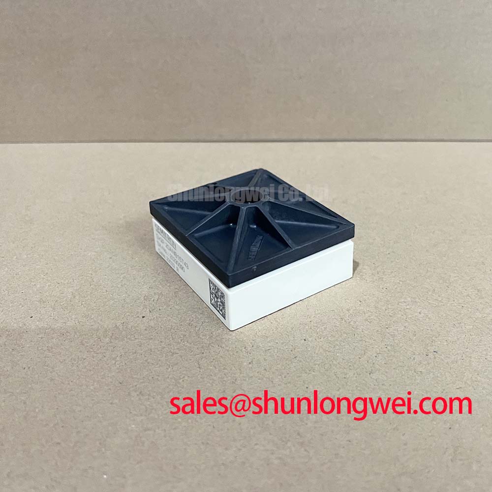
The Semikron SKIIP 20ANB15T43 is a CIB power module combining a three phase rectifier, a three phase inverter, and a brake chopper. Before commissioning or replacement, verify its electrical ratings, terminal assignments, gate drive requirements, and temperature sensing connections against the manufacturer’s datasheet for the exact part number. The part marking alone should not be used to infer operating voltage, continuous current capability, or integrated protection functions.
| Parameter | Product Information or Verification Requirement |
|---|---|
| Manufacturer | Semikron |
| Model | SKIIP 20ANB15T43 |
| Topology | CIB: three phase rectifier, three phase inverter, and brake chopper |
| Collector emitter voltage | Verify the maximum rating in the exact-part datasheet |
| Continuous collector current | Verify the rating and its case temperature and operating conditions |
| IGBT technology | Verify the technology designation in the exact-part datasheet |
| Gate drive, protection, and sensing | Confirm the module connections and the functions provided by the associated driver and controller |
| Isolation voltage | Verify the specified voltage, test duration, and test configuration |
In a precision stepper or BLDC motor servo actuator, the brake chopper can route regenerated energy toward a braking resistor when the DC link rises during deceleration. The resistor, switching frequency, DC link control, and thermal enclosure determine how much energy the complete system can absorb. The module rating alone does not establish a permissible braking profile, so commissioning should correlate the chopper command, DC link waveform, resistor temperature, and motor deceleration sequence.
SKIIP 20ANB15T43 Operational Boundaries: Mechanical Loading and Braking
Mechanical loading at the assembly’s main power connections deserves attention before electrical testing because cable movement and vibration can transfer force into the module connections. A connection that appears electrically sound during a cold resistance check can still have poor mechanical support.
Start by checking that each power conductor approaches its connection without forcing a bend immediately above it. Where bolted lugs are used, the lug should sit flat, and the washer should apply pressure across the intended contact area rather than resting on a raised edge or damaged surface. Compare the installed hardware with the original assembly, including washer type, bolt length, and any support bracket used to restrain heavy cables. A loose cable bundle can create a levering action during motor acceleration and regenerative braking.
Field Alert: De energize and isolate all power sources, follow the equipment discharge procedure, and verify that the DC link is at a safe voltage before removing cables or touching the power connections.
Torque reaction from a servo actuator is not confined to the motor shaft. Rapid changes in load can produce movement in the cabinet, busbar assembly, and cable harness. Design Consideration: provide mechanical strain relief outside the module so that electrical connections do not carry cable weight. The final fastening method remains determined by the hardware specification and the equipment manufacturer’s assembly procedure.
During a replacement, photograph the original routing before disconnecting the module. Mark the positive bus, negative bus, phase outputs, rectifier inputs, brake connection, gate driver connections, and NTC leads. CIB modules contain several functional sections in one housing, so a wiring error can place a measurement point on the wrong part of the topology. A cold inspection should include the brake resistor path because an open resistor, damaged contactor, or failed precharge arrangement can change the DC link behavior even when the replacement module is correctly installed.
The brake chopper should be evaluated as part of the energy path, not as an isolated switch. When the actuator decelerates, monitor whether the DC link rises smoothly, whether the brake command appears at the expected operating point, and whether the resistor receives the intended load without abnormal acoustic or thermal behavior. The switching threshold, pulse width, and thermal duty are system parameters. Engineers should verify them with the controller documentation and switching measurements rather than inferring them from the module’s voltage rating.
For a neutral comparison during procurement or repair planning, the PM20CVL060-33 may be reviewed as a separate power module reference. It should not be treated as an automatic substitute because topology, voltage class, gate interface, protection behavior, terminal arrangement, and mechanical envelope must all match the original installation.
Field Diagnostics & Commissioning: Separating Driver Return from Main Current in SKIIP 20ANB15T43 Topologies
Gate driver return routing is central to stable switching because the high current emitter path and the driver reference do not experience the same voltage during rapid current transitions. Where the assembly provides a dedicated low inductance driver return, that connection should be traced directly to the driver circuit rather than joined casually into a long power conductor. The exact terminal designation must be taken from the module drawing and the equipment wiring record.
With the module isolated, use continuity and resistance checks to map the installed driver loop against the known-good wiring. Avoid treating a low resistance reading as proof that the return path is suitable at switching speed. A long shared conductor can show excellent DC continuity while developing transient voltage during current commutation. Oscilloscope probing should compare the gate to its intended driver reference at the module terminals, using appropriately rated differential or isolated probes and a connection technique that does not add a misleading loop.
Driver functions such as UVLO and Vce(sat) protection, where provided by the associated gate drive, do not replace correct controller timing or layout. The controller must prevent simultaneous conduction where the topology requires complementary switching. Dead time, pulse blanking, fault reset behavior, and gate resistance are system commissioning parameters. Engineers should confirm the actual timing at the gate and collector emitter waveforms under the intended DC link and motor load.
Gate loop parasitic inductance can create voltage movement at the driver reference and may contribute to false triggering, ringing, or an unexpected protection response. The practical correction is to shorten the high di/dt loop, separate power and signal routing, and keep the driver return with its associated gate path. The final layout should be validated through switching tests that check gate amplitude, turn off behavior, collector emitter overshoot, and fault recovery.
Thermal interface installation must be treated as a controlled mechanical operation. The heatsink face should be clean, flat, and free from burrs. Design Consideration: a thin, continuous thermal interface layer is generally preferable to thick areas or uncovered patches; use the material and application thickness specified in the applicable assembly instructions. The actual result depends on surface flatness, material rheology, and the specified clamping system. Excess compound can reduce mechanical repeatability and contaminate nearby insulation surfaces.
Follow the module assembly documentation for the mounting sequence and torque. Where a multi point mounting arrangement calls for progressive tightening, avoid loading one corner first. Record the sequence used during service. If the heatsink is distorted, the thermal contact surface may not contact evenly even when every fastener appears tight. After assembly, inspect the squeeze pattern at the edge of the interface where practical and confirm that the module is seated correctly.
During first power application, keep the motor unloaded where the equipment permits and observe the NTC reading, driver fault state, DC link rise, and phase output behavior. A fault indication should be correlated with the control supply, driver return, and power circuit rather than assigned to one cause immediately. The Semikron-Danfoss SEMITRANS® Industry Standard IGBTs reference provides general manufacturer context for industrial power semiconductor families, not an exact-part specification, while ROHM Dedicated Gate Driver ICs for IGBT/SiC offers relevant background on gate driver design considerations.
Assembly Integrity & Layout Architecture: Insulation Screening for SKIIP 20ANB15T43
Insulation screening should begin with the module disconnected from the controller, DC link, motor, brake resistor, and measurement equipment. Check the power circuit to heatsink or mounting surface insulation only using the test configuration, voltage, and procedure permitted by the module and equipment documentation. Use the documented acceptance criteria; a production isolation rating is not automatically an authorized maintenance test voltage.
A changing insulation reading can result from surface contamination, moisture, connected circuitry, probe placement, or internal damage. Clean and dry the accessible insulating surfaces, isolate all external paths, and repeat the test under controlled conditions. Compare phase groups and terminal groups as appropriate for the documented test configuration, recording that configuration each time. Do not apply an insulation test through the gate driver or controller unless those circuits are specifically rated for the applied test.
Cracking in a ceramic substrate or separation within a power assembly may not be visible from the outside. Mechanical distortion, thermal cycling, uneven clamping, and contamination across creepage surfaces can all affect field behavior. A visual inspection should therefore examine the accessible mounting surfaces, terminal housing, solder joints visible from the service side, discoloration, tracking marks, and signs of coolant or oil exposure. Any physical damage should be correlated with electrical measurements and the equipment history rather than treated as a single definitive failure mechanism.
Creepage and clearance around the high voltage terminals must remain free from conductive dust, loose hardware, and residue from excessive thermal compound. The cabinet layout should preserve the original spacing and barriers, especially around the rectifier input, DC link, brake chopper, and inverter outputs. If the module is being moved to a different heatsink or enclosure, the system designer must re-evaluate insulation coordination, airflow, contamination level, and accessible service surfaces.
The NTC sensor should be checked through its designated circuit and compared with the equipment’s temperature monitoring response. An implausible temperature indication can arise from a disconnected sensor, incorrect connector placement, damaged wiring, or controller scaling. Verify the sensor path before authorizing high current operation. Thermal performance also depends on heatsink capacity, airflow, contact pressure, switching duty, and brake resistor energy, so the NTC reading should be reviewed alongside the heatsink temperature and operating waveform.
For longer service evaluations, document the DC link level, motor current, braking events, heatsink temperature, fault history, and insulation results at each intervention. The Field Engineer’s Handbook can be used as a practical reference for structured testing and failure analysis. This record gives the repair team a traceable basis for deciding whether the issue is concentrated in the power module, the gate drive, the brake circuit, the cooling interface, or the wider actuator system.