




Content last revised on October 23, 2026
Preventing Spurious Faults: Thermal Time Constants and Peak Junction Guidelines for SKIIP31NAB125T12
With the DC link discharged and verified safe, isolate the SKIIP31NAB125T12 from parallel circuit paths before comparing cold terminal readings with the equipment schematic. Record the measurement polarity and allow charging effects to settle; an unexpected reading is a reason to investigate the connected circuit, not sufficient evidence to condemn the module.
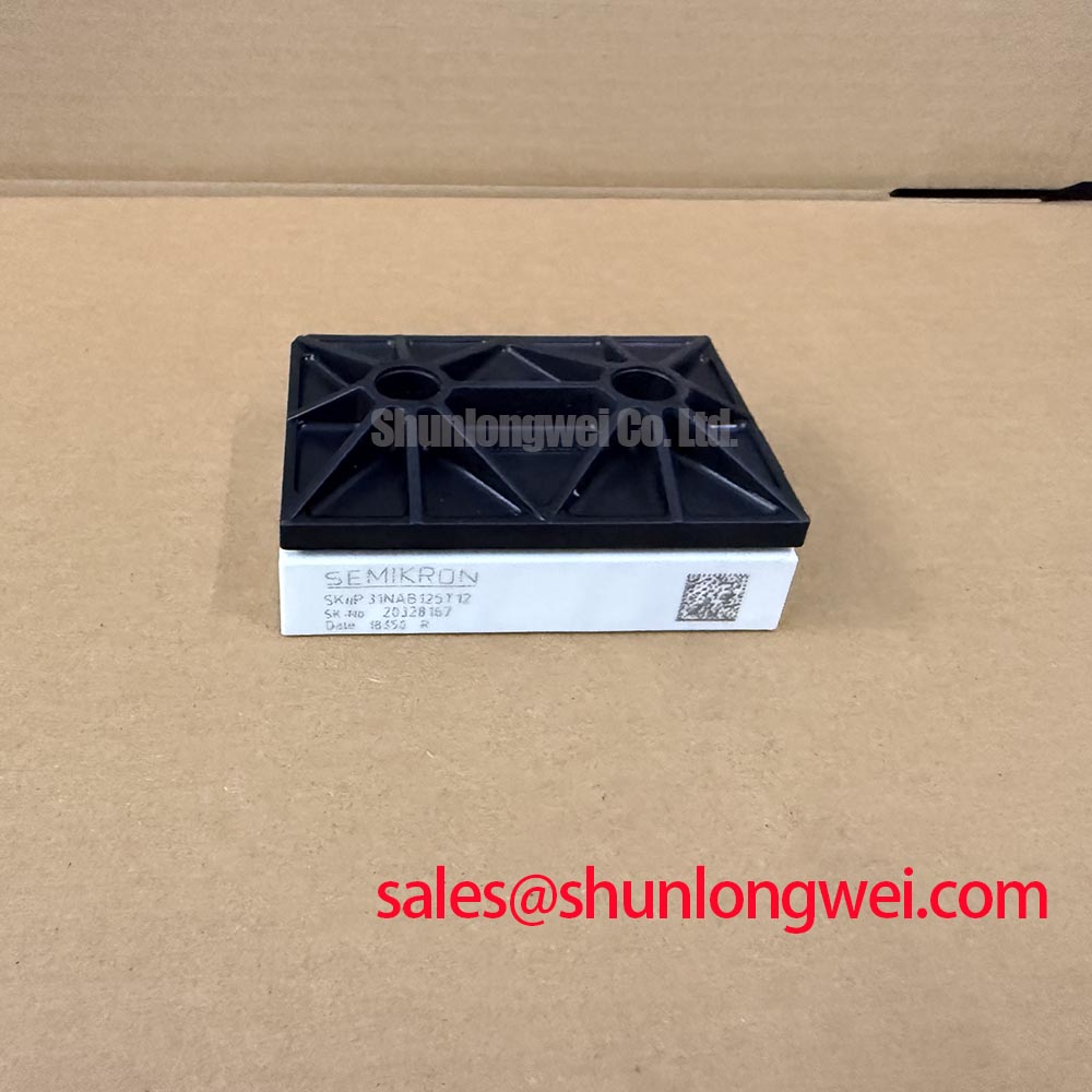
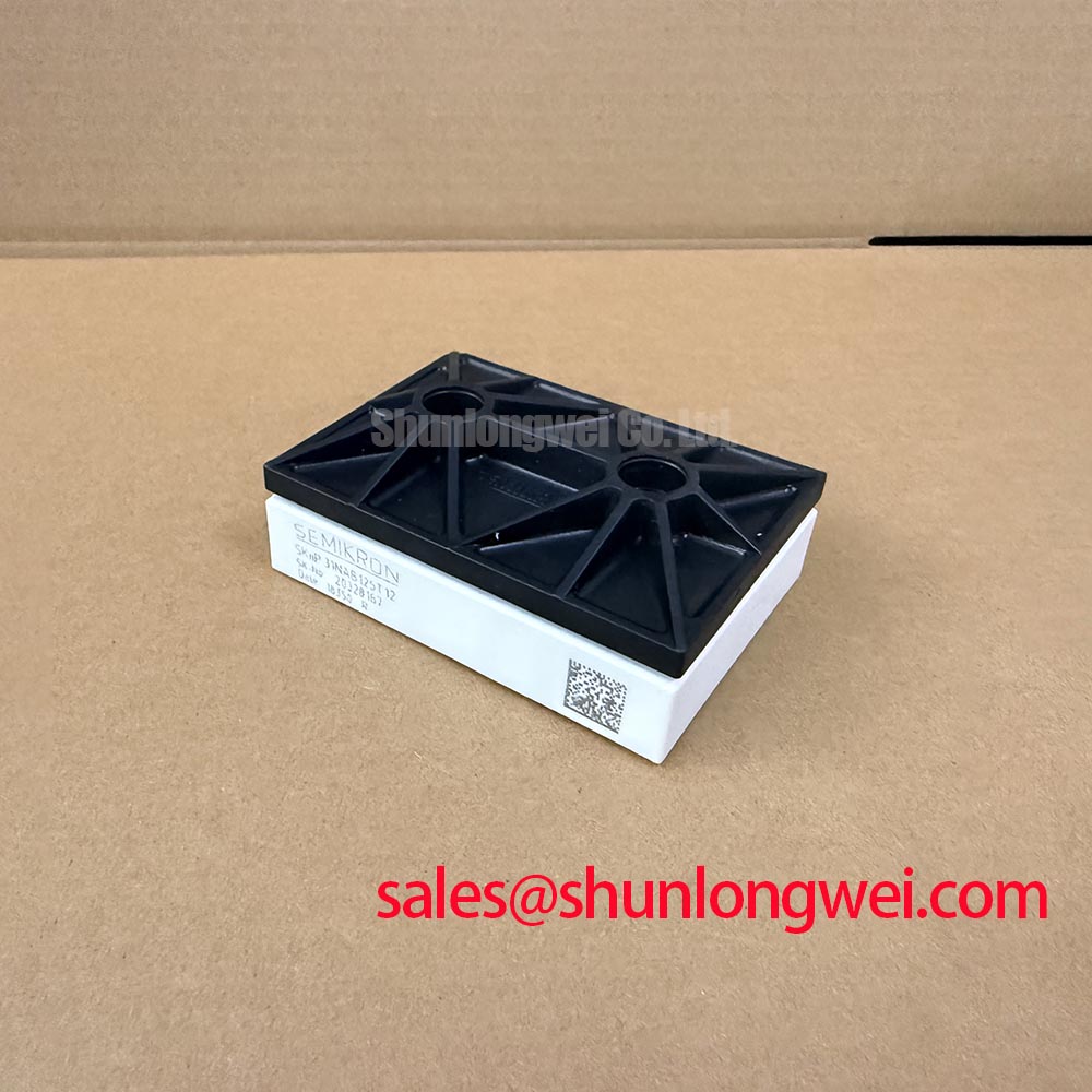
The SKIIP31NAB125T12 is a 1200 V-class MiniSKiiP module from Semikron. These establish the starting point for identification. Confirm the current rating and its applicable conditions in the device-specific datasheet. Replacement assessment also requires the terminal map, circuit configuration, mechanical interface, and operating conditions. The IPM procurement category should not be interpreted as confirmation of integrated gate drivers or protection functions.
Capture the overload duration and repetition pattern alongside the heatsink temperature when investigating temperature-related trips. As a Design Consideration, a short current pulse can produce a junction-temperature excursion that is poorly represented by a slowly responding heatsink sensor. Comparing trip events only with cabinet temperature can therefore overlook the relevant thermal transient.
For an Engineering Calculation, a documented multi-RC thermal model represents transient thermal impedance as the sum of thermal-resistance branches, each responding according to its associated time constant. Apply the estimated semiconductor loss waveform to that response and add the appropriate thermal-reference temperature to obtain junction-temperature history. Peak margin is then assessed against the documented junction limit. The model coefficients, thermal reference, and loss conditions must belong to the applicable device documentation; coefficients from another MiniSKiiP module are not interchangeable.
On the service bench, preserve the original overload profile rather than substituting an arbitrary continuous load. Compare the temperature response during acceleration, steady operation, and recovery. As a Design Consideration, repeated pulses can accumulate heat before the assembly returns to its initial temperature, so examining a single isolated pulse can understate the peak reached during repetitive duty.
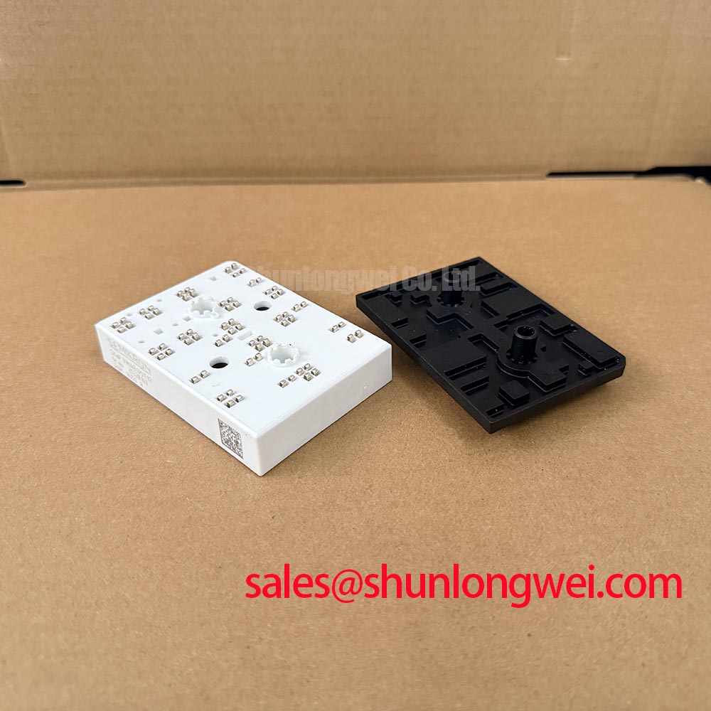
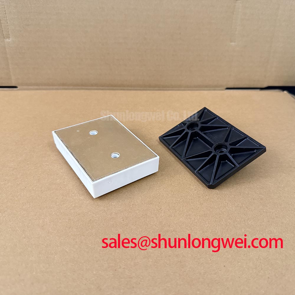
Inspect the heatsink contact surface for contamination, uneven witness marks, and mechanical interference. Check that the module seats without enclosure hardware or nearby components holding it away from the intended mounting plane. The manufacturer’s Semikron MiniSKiiP® Power Modules information provides product-family context for the mounting concept; the module-specific assembly instructions govern the actual installation.
Field Alert: Follow the applicable module mounting instructions for tightening sequence and thermal-interface application rather than transferring torque settings from a visually similar package.
Do not introduce disc springs, press-pack pressure adjustments, or double-sided cooling procedures unless the actual assembly documentation requires them. As an Engineering Recommendation, restore the documented thermal interface first, then repeat the recorded load cycle while observing temperature and protection status. This separates an assembly-related thermal problem from a load-dependent electrical loss issue without inventing a temperature threshold.
Transient Dynamics & Electrical Design: Pollution Degree 3 Creepage Distances on SKIIP31NAB125T12
Inspect exposed insulating surfaces and terminal regions for conductive deposits before assessing the installation’s creepage requirements. Pollution Degree 3 is an insulation-coordination condition, not a qualification established by the 1200 V module rating. As a Design Consideration, required creepage depends on the applicable equipment standard, working voltage, insulating material characteristics, and the actual local environment.
Trace the external surface paths between power conductors and accessible conductive hardware, including paths across the carrier board and mounting assembly. Dust accumulation, moisture, and residue can change the condition of those paths. Cleaning and reassembly should follow the equipment service procedure, with attention to connector seating and contamination trapped beneath surrounding hardware.
An insulation-resistance test requires an approved test configuration, including which terminals are connected together and which circuits must be disconnected. Do not adopt a generic megohmmeter voltage or acceptance resistance as an SKIIP31NAB125T12 specification. As an Engineering Recommendation, use the manufacturer-authorized test procedure and isolate sensitive electronics as directed. A terminal-to-heatsink measurement alone does not establish the integrity of a particular internal ceramic construction.
The Semikron-Danfoss SKiiP® Technology reference provides background on the technology family, but it does not replace a device-specific insulation test specification. Keep family-level information separate from acceptance criteria for an individual repair.
During replacement assessment, compare the original SKIIP31NAB125T12 against any candidate by circuit function and interface before comparing headline ratings. The related SKIIP82AC121T1 is a cross-model comparison reference, not an established drop-in substitute.
| Comparison item | SKIIP31NAB125T12 | SKIIP82AC121T1 |
|---|---|---|
| Manufacturer | Semikron | Semikron |
| Rated voltage | 1200 V | Consult datasheet |
| Rated current | Consult datasheet for rating and applicable conditions | Consult datasheet |
| Package designation | MiniSKiiP | Consult datasheet |
| Replacement acceptance | Match original circuit and assembly requirements | Establish topology, pinout, mounting, thermal, and driver compatibility |
Compact industrial inverters and high-speed CNC spindle drives are potential compatibility-assessment examples, subject to those checks. A device such as SKM150GAL12T4 should likewise be evaluated by its documented circuit function; its presence in a power-module catalogue does not establish suitability as the input rectifier or companion stage.
For fuse coordination, compare the protective device’s clearing behavior with the applicable semiconductor withstand information and available fault current. As a Design Consideration, fuse I²t alone does not establish transistor short-circuit protection. Driver detection and controlled shutdown must address the semiconductor fault interval, while the fuse’s role is evaluated within the complete fault-clearing arrangement.
Preventing Spurious Faults: Gate Driver Auxiliary Power Sequencing Guidelines for SKIIP31NAB125T12
Record the driver auxiliary supply, gate-to-emitter voltage, enable signal, and fault output through startup and shutdown. As an Engineering Recommendation, verify that the equipment’s intended gate-off state is established before switching is enabled and remains controlled while the DC link decays. Evaluate the actual UVLO and interlock sequence rather than assuming that an illuminated driver-board indicator proves readiness.
Negative gate bias, where specified by the original driver design, must be assessed against the applicable gate limits and measured transient behavior. Do not assign a generic negative-bias range to this module. As a Design Consideration, common-mode current and shared return-path impedance can disturb the measured gate waveform; measure at the relevant gate and emitter connections with suitable probing and examine whether the disturbance coincides with opposite-switch transitions.
Review desaturation detection and soft shutdown together. Desaturation monitoring observes collector-emitter behavior under defined drive conditions; it is not interchangeable with the steady-state VCE(sat) specification. As an Engineering Recommendation, verify the documented detection blanking, fault propagation, and controlled turn-off behavior against the device’s applicable short-circuit safe operating area. Avoid forcing a short circuit during routine field diagnosis.
Check dead time at the actual gate waveforms when investigating suspected cross-conduction. Propagation differences, turn-off behavior, and driver supply movement all affect the effective interval. If the equipment schematic includes a bootstrap supply, inspect its charging path and capacitor condition, then observe supply recovery through the intended switching pattern. Bootstrap droop or diode recovery effects require waveform evidence, not diagnosis from a fault code alone.
The technical discussion in Unlocking Efficiency in Industrial Drives offers background on switching-loss and drive-system tradeoffs; it does not identify SKIIP31NAB125T12 as an IGBT7 device. For the installed module, keep gate-loop routing compact and separate sensitive returns from power-current paths, with the final arrangement verified under representative switching conditions.
Where a long motor cable is present, distinguish motor-terminal reflection effects from collector-emitter overshoot at the module. As a Design Consideration, measure at the location relevant to the suspected stress using appropriately rated equipment. Evaluate any output filter against the cable, motor insulation requirements, and inverter control strategy, then repeat the operating condition that originally produced the fault.