Content last revised on September 20, 2026
Benchtop Waveform Tuning: Mitigating Stress via DC Bus Low Inductance Laminated Busbar Design on SKM150GAL12T4
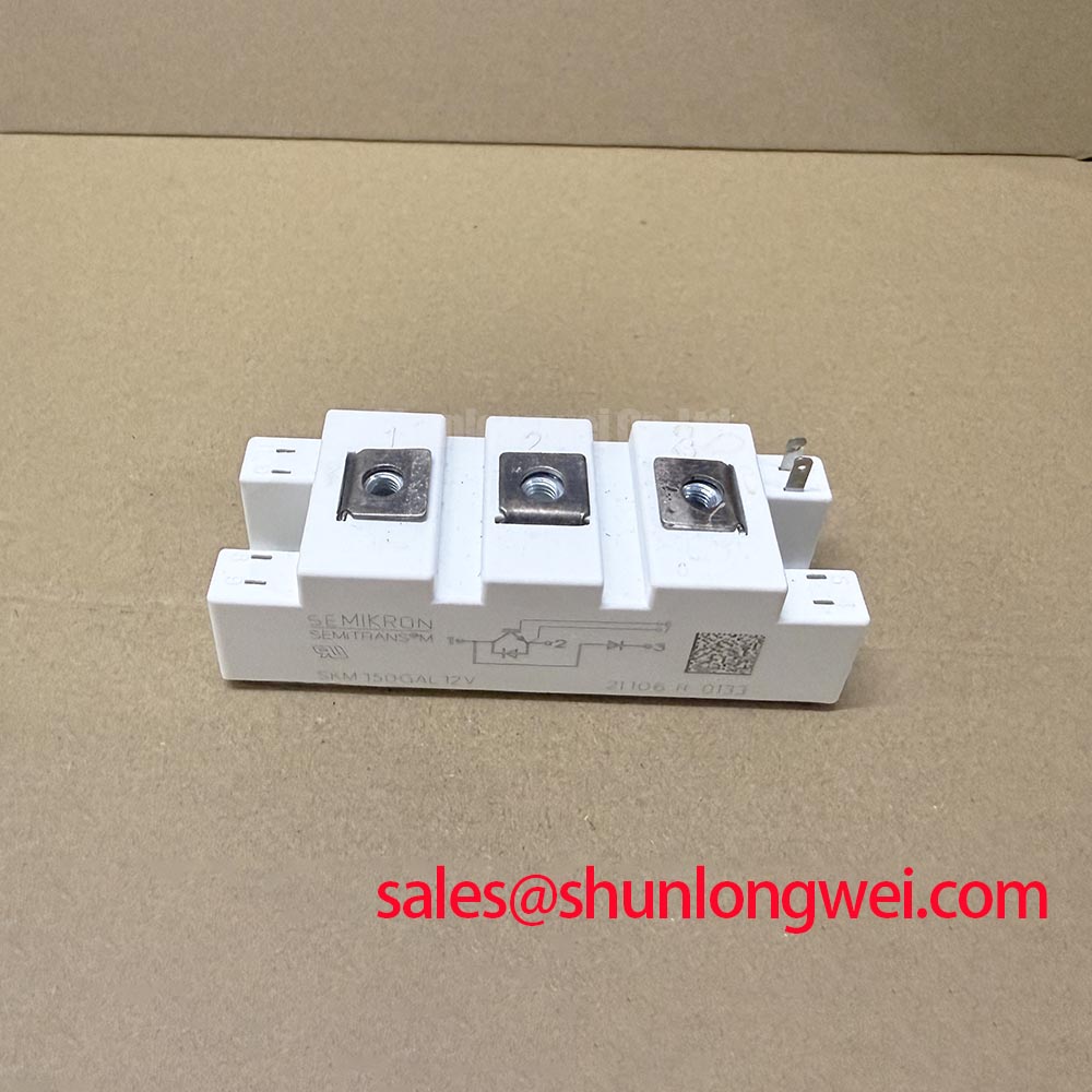
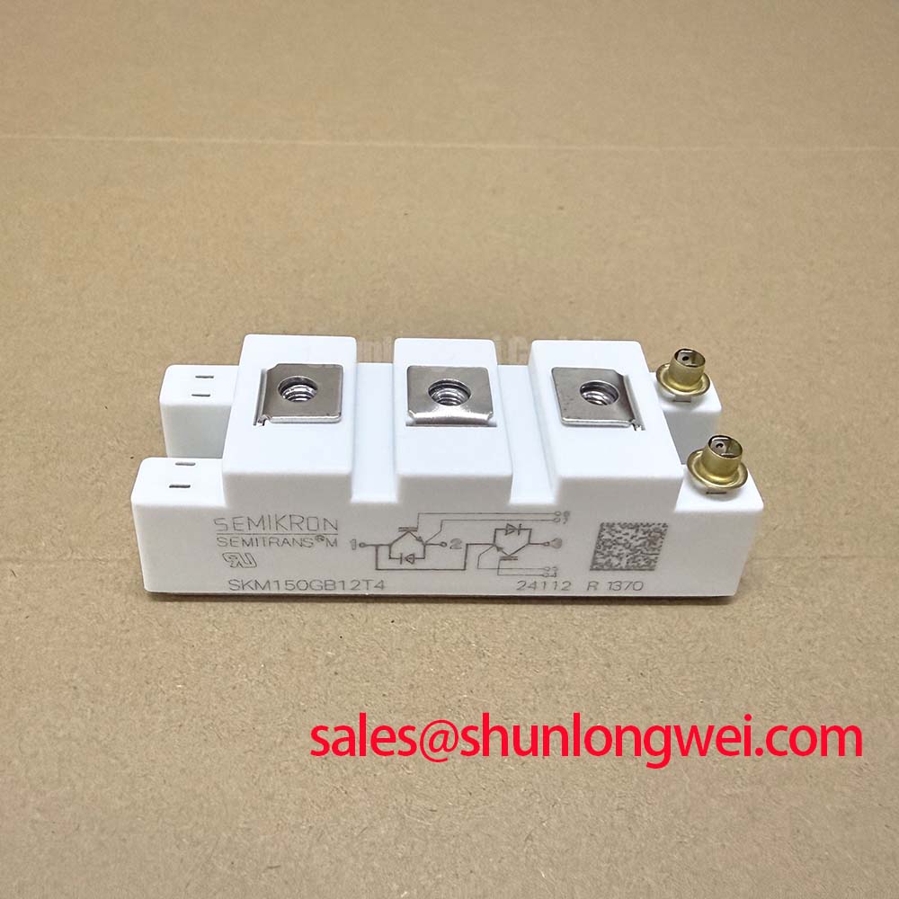
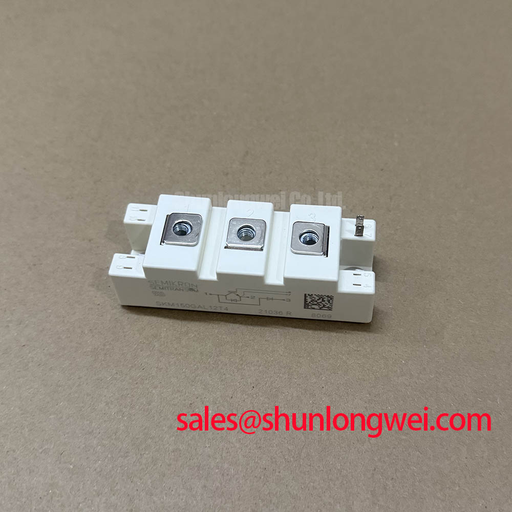
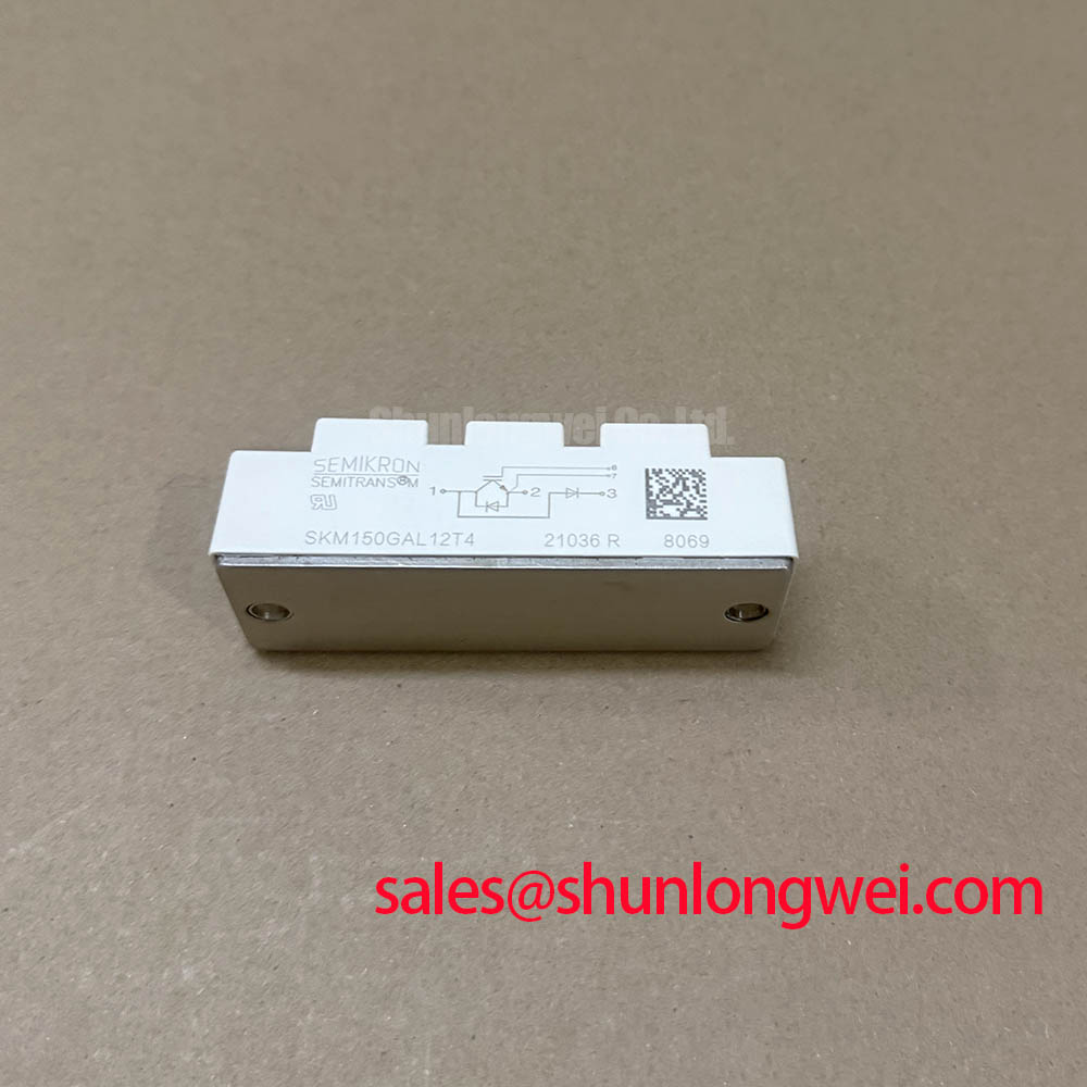
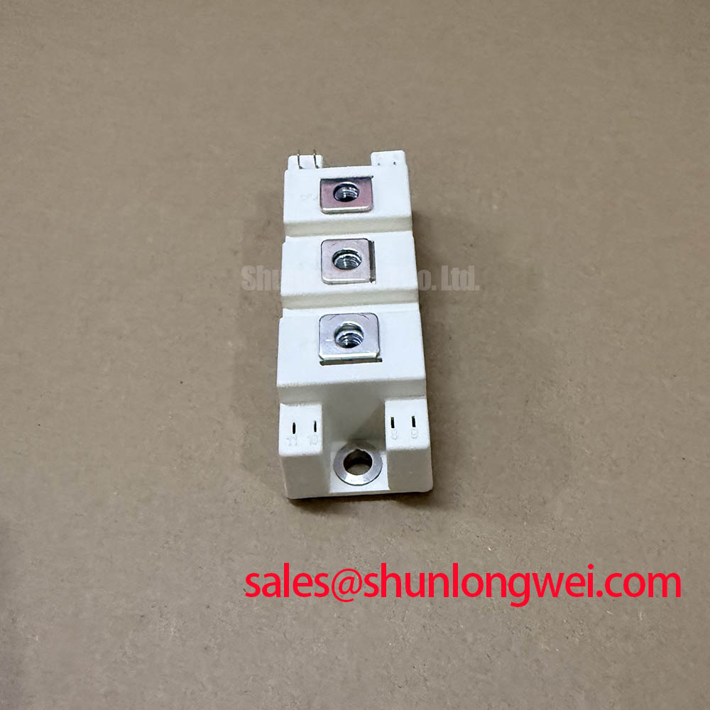
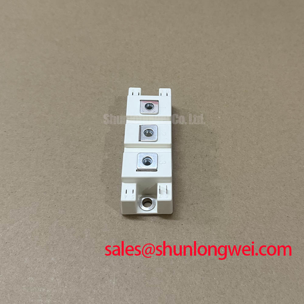
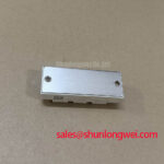
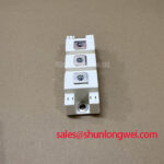
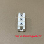
Before reconnecting the DC link, isolate the drive, discharge the energy-storage circuit by the machine builder's approved method, and compare the module marking with the drive documentation. The SKM150GAL12T4 is a Semikron IGBT module in the SEMITRANS 2 package, rated at VCES = 1200 V and IC = 150 A at Tcase = 80 degrees C as Official Datasheet Specifications. For maintenance work on a heavy-duty variable frequency AC motor drive, these ratings establish the device boundary to verify before evaluating the gate-drive board, DC-link assembly, cooling path, or motor-output network.
Its official maximum collector current is ICM = 300 A, while total power dissipation is specified as Ptot = 835 W at Tcase = 25 degrees C. The official maximum junction temperature is Tjmax = 175 degrees C. These values do not define an unrestricted operating condition; the actual permissible current, switching behavior, and temperature margin depend on the complete converter topology, switching conditions, heatsink performance, gate drive, and measured thermal response.
| Official Specification | Value |
|---|---|
| Product model | SKM150GAL12T4 |
| Manufacturer | Semikron |
| Collector-emitter voltage, VCES | 1200 V |
| Continuous collector current, IC, at Tcase = 80 degrees C | 150 A |
| Maximum collector current, ICM | 300 A |
| Total power dissipation, Ptot, at Tcase = 25 degrees C | 835 W |
| Maximum junction temperature, Tjmax | 175 degrees C |
| Package | SEMITRANS 2 |
Start waveform work with the module installed in the intended power loop and the probe arrangement qualified against a known switching node. A long ground lead on a voltage probe can introduce apparent ringing that does not represent the collector-emitter stress at the SKM150GAL12T4 terminals. Differential measurement with a suitably rated probe and a compact probing loop gives a more defensible view of switching overshoot, ringing frequency, and the relationship between gate command and collector-emitter voltage.
Design Consideration: turn-off overshoot rises with stray inductance and current transition rate. In engineering terms, peak voltage contains the DC-link voltage plus an inductive contribution related to loop inductance multiplied by the rate of current change. The practical task is to reduce the physical area enclosed by the DC-link capacitor, busbar, and module current path, then verify the resulting peak voltage during controlled switching tests. Laminated busbars are often evaluated because closely coupled outgoing and return conductors reduce loop inductance while keeping the DC-link path geometrically consistent.
Place the local DC-link connection as close to the module power terminals as the converter structure permits. Avoid routing a high-current supply conductor outward and returning it on a separate distant plane, because the larger magnetic loop can increase switching stress and radiated disturbance. Busbar bends, terminal interfaces, capacitor interconnects, and fastening surfaces should be reviewed as one current path rather than as isolated mechanical parts. The system engineer should verify clearances, insulation coordination, and peak voltage margins for the actual installed DC bus voltage and enclosure conditions.
Where measured turn-off ringing remains significant, examine the sequence of events instead of assigning one cause. A gate-drive network, DC-link connection, capacitor placement, probe method, module temperature, and load current can all influence the observed trace. Snubber capacitors or other suppression networks are a Design Consideration that require validation in the finished converter, including capacitor RMS-current capability, thermal behavior, voltage rating, and the change in switching loss. A suppression part that improves one waveform at low load can produce a different result at production current or temperature.
During repair, inspect for discoloration near busbar contact areas, loosened hardware, cracked support insulators, and evidence that a conductor has moved toward another conductive structure. These observations do not establish a single failure mechanism, but they identify conditions worth correcting before a replacement module is energized. For a lower-current comparator within a different voltage class and package arrangement, engineers can review the published details of SKM75GB07E3; terminal layout, electrical rating, thermal interface, and gate-drive requirements must still be verified independently.
Assembly Integrity and Layout Architecture: Implementing Baseplate Thermal Grease Layer Control for SKM150GAL12T4
Clean the heatsink contact surface and the module baseplate with a process-approved residue-free method before installing the SEMITRANS 2 module. Check both mating surfaces under suitable light for embedded particles, raised burrs, corrosion, old hardened interface material, or local damage that could prevent even contact. The 835 W at Tcase = 25 degrees C official dissipation rating is not a substitute for a verified thermal path in the assembled drive. The relevant operating condition is the measured relationship among module case temperature, heatsink temperature, cooling-air condition, load profile, and switching losses.
Engineering Recommendation: apply thermal interface material as a controlled, continuous layer according to the material supplier's process guidance and the equipment documentation. The objective is to fill microscopic surface irregularities without creating an excessively thick layer that adds thermal resistance. Use a repeatable stencil, roller, or specified application tool where the maintenance process supports it. After removal of a previously installed module, do not assume the old grease pattern proves acceptable contact quality; inspect the distribution and address any obvious local dry areas or trapped debris.
Mounting hardware should be tightened in the sequence and torque specified by the relevant mechanical documentation for the module, heatsink, and hardware set. Crosswise tightening in progressive passes is a Design Consideration that helps establish even baseplate contact while avoiding a large local mechanical load during installation. The actual torque value must be taken from the applicable Semikron documentation and the equipment manufacturer's assembly procedure, because screw size, thread engagement, washer arrangement, and heatsink construction determine the acceptable setting.
Verify power-terminal assignment directly from the original drive drawing and the applicable module documentation before connecting busbars. Do not infer terminal function from cable orientation, an earlier repair, or an apparently similar housing. Check that busbars sit flat, fastening hardware is complete, and adjacent conductive structures retain the clearances required by the system design. Where vibration is relevant to the equipment, use the approved retention method and inspect busbar supports for movement, fatigue, or distortion during planned maintenance.
Maintenance Note: Periodically monitor terminal contact temperature rise and confirm that the cooling-air path remains free of dust accumulation and blocked flow.
Condensation control also belongs in the assembly review. A cool module or heatsink brought into a warm humid enclosure can accumulate moisture before power is applied. Allow environmental conditions to stabilize according to site practice, inspect for visible moisture, and verify cabinet sealing, heater operation where fitted, and drainage provisions. These checks are preventive maintenance measures, not a statement of a specific environmental qualification for the SKM150GAL12T4.
SKM150GAL12T4 Operational Boundaries: Evaluating Differential Gate Source Loop Routing to Limit Switching Instability
Gate-drive routing should be examined with the power loop rather than treated as a low-energy control detail. A gate signal that shares impedance with the high-current emitter return can experience a voltage disturbance when load current changes rapidly. That disturbance can alter the effective gate-emitter voltage seen by the switching device and may contribute to unexpected turn-on, delayed turn-off, or oscillatory behavior. The system integrator should verify the terminal arrangement and any available control-reference connection from the original module documentation before changing the existing gate-drive wiring.
Design Consideration: keep the gate-command path and its intended return compact, direct, and separate from high-current power-return conductors where the topology provides the required connection points. This reduces common impedance coupling during switching. Cable length, connector condition, driver-board placement, gate resistance, and gate-driver output capability all affect the final result, so no universal component value should be applied without measured confirmation. Oscilloscope traces of gate-emitter voltage and collector-emitter voltage, captured at the relevant operating point, provide a stronger basis for adjustment than a visual assessment of wiring alone.
For protection review, confirm that the gate driver and controller implement the behavior specified by the original equipment design. A desaturation or collector-emitter monitoring function, where used by the drive, must be evaluated with its blanking interval, sensing path, fault reporting, and controlled turn-off behavior as an integrated protection system. It is not appropriate to infer short-circuit withstand capability, soft turn-off timing, or safe operating limits for this module from the listed voltage and current ratings alone. The original Semikron technical data and the drive designer's protection requirements govern that evaluation.
The 1200 V collector-emitter rating is an Official Datasheet Specification, but switching peaks need to remain within the system's verified transient limits. Gate-loop changes can affect both voltage overshoot and electromagnetic disturbance, particularly when freewheel-diode recovery and commutation conditions are changing. Review conducted and radiated emissions at system level where compliance is required. An individual IGBT module is not, by itself, a certified complete EMC system.
For broader context on power-device switching efficiency and system-level design decisions, consult Unlocking Efficiency in Industrial Drives. Semikron-Danfoss also provides product-family context through its SEMITRANS industry-standard IGBT module information. These references support technical comparison, while the exact characteristics and terminal configuration of SKM150GAL12T4 must be confirmed against the applicable product documentation.
Field Diagnostics and Commissioning: Long Motor Lead Reflected Wave Voltage in SKM150GAL12T4 Topologies
Before commissioning a drive with a long motor cable, document the cable route, approximate length, motor connection condition, output-filter arrangement, and measurement points. Fast inverter switching transitions can interact with cable impedance and motor-terminal impedance, producing reflected-wave behavior at the motor end. Under certain transmission-line conditions, voltage peaks approaching twice the DC-link voltage can occur at the motor terminals. This is a system phenomenon, not an official voltage rating or a guaranteed waveform outcome for the SKM150GAL12T4.
Use suitable differential measurement equipment at both the inverter output and, where safe and practical, the motor terminals to distinguish converter-side switching stress from cable-end reflections. Compare phase-to-phase and phase-to-earth behavior where the maintenance procedure permits. An unexpected waveform may indicate several possible conditions, including cable termination characteristics, output-filter condition, motor insulation condition, grounding arrangement, probe placement, or a change in switching behavior. Verify findings against a known-good drive path or controlled baseline whenever available.
Design Consideration: a dv/dt filter, sine-wave filter, or output choke may be evaluated when the motor cable and motor insulation system require reduced terminal stress. Selection must be determined by the drive voltage, switching frequency, motor current, cable characteristics, filter losses, control performance, and the machine builder's requirements. Confirm the filter's current and thermal capability under the actual duty cycle. Do not install an output network solely because a waveform appears visually sharp on an improperly referenced scope trace.
Commission the repaired drive progressively under the approved safety process. Confirm correct rotation and low-load behavior before testing the intended load profile, while monitoring cooling performance, supply stability, and fault response. The official IC = 150 A at Tcase = 80 degrees C rating should be interpreted together with the actual heatsink and duty conditions. Repeated thermal cycling can be reduced through stable cooling airflow, clean thermal interfaces, secure electrical contacts, and operating conditions verified by the system owner.
For authoritative product-family and power-electronics information, refer to the Semikron-Danfoss Power Electronics and Modules official hub. During field diagnosis, retain measured waveforms, case-temperature observations, controller fault records, and cooling-system findings with the maintenance record. This evidence supports a disciplined repair decision without assigning a single unverified cause to an observed fault.