


Content last revised on October 1, 2026
SKIIP38AC12T4V1 Gate Switching and Thermal-Electrical Checks
| Product | SKIIP38AC12T4V1 |
|---|---|
| Manufacturer | Semikron |
| Product category | IPM |
| Package | MiniSKiiP / SKiiP |
| Rated voltage | 1200 V |
| Rated current | 38 A |
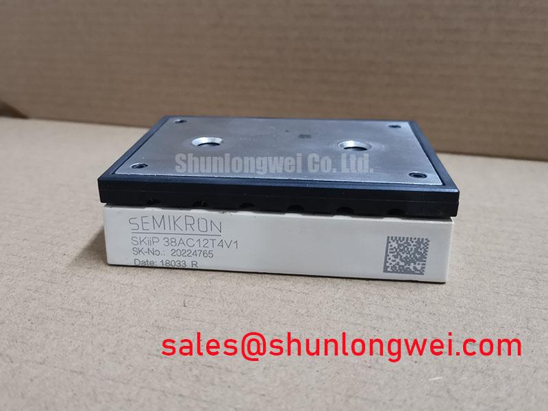
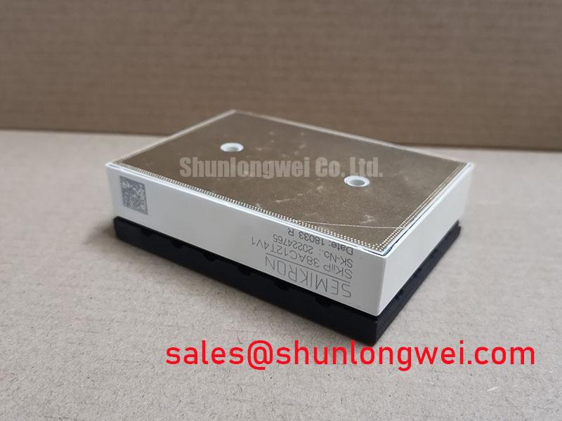
With the drive isolated and its DC link discharged, inspect the module terminals and surrounding board for heat damage, loose connections, contamination, or cracked solder joints before reconnecting control power. Confirm the installed part marking is SKIIP38AC12T4V1, then compare the drive schematic and the removed module’s terminal arrangement with the replacement documentation. The stated 1200 V voltage rating and 38 A current rating identify key module ratings; they do not, by themselves, establish compatibility with a particular inverter or motor.
During commissioning, capture gate-to-emitter and switching-node waveforms with probes and measurement connections suitable for the circuit’s voltage and common-mode transients. Look for unintended gate movement during the opposite switch’s turn-on and turn-off, excessive ringing, or inconsistent switching between phases. These observations can point to a drive, layout, grounding, or module issue; they do not establish a single cause without checking the full signal path. Compare results with the equipment’s known-good records and the applicable module and gate-driver documentation.
Design Consideration: Fast voltage transitions can couple through parasitic capacitances and disturb gate control. A low-impedance gate-off path or an active Miller clamp may be considered when the circuit exhibits unwanted turn-on, but the appropriate driver topology and gate bias must be established from the module’s official data and verified under the actual switching conditions. Do not apply a negative gate voltage based on a generic recommendation; confirm permitted gate limits and the driver interface first.
Inspect gate-loop routing and power-loop geometry for long, shared return paths or close coupling between high-current switching nodes and control signals. Keep the control reference arranged according to the module and driver documentation, and check that measurement-probe connections are not adding misleading loop inductance. Any layout change should be followed by switching tests that verify gate behavior, overshoot, and thermal performance across the operating range.
The Semikron MiniSKiiP power module family information provides product-line context. For this exact module, use its applicable datasheet and the equipment manufacturer’s wiring documentation to establish terminal functions, gate limits, switching conditions, and installation requirements.
SKIIP38AC12T4V1 Overvoltage Protection and Motor-Lead Assessment
When a motor drive reports overvoltage or shows abnormal switching-node peaks, record the DC-link voltage and phase output waveforms during the event, then compare them with the drive’s documented operating limits. Check motor-cable routing, length, shielding and termination against the inverter and motor manufacturers’ instructions. Cable reflections and circuit parasitics can contribute to terminal stress, but the measured waveform and system configuration determine whether an output reactor, dv/dt filter, or other mitigation is appropriate.
Engineering Recommendation: Evaluate a filter or reactor as part of the complete inverter–cable–motor system, rather than selecting one from the module’s voltage rating alone. Confirm its compatibility with the drive’s switching behavior, motor insulation requirements, protection settings, and thermal limits. Validate any change by measuring the relevant waveforms at the inverter and motor terminals under representative load conditions.
For DC-link clamping or surge protection, assess the MOV or other suppression network against the system’s normal bus voltage, transient energy, coordination requirements, and the drive manufacturer’s protection scheme. A device’s nominal voltage or energy rating alone does not demonstrate suitable coordination. Confirm that the selected network will not interfere with normal operation or create an unacceptable fault-current path, and review its condition if repeated transients or visible damage are found.
Semiconductor fuse coordination also requires system-level evidence. Compare the fuse’s time-current behavior and I²t characteristics with the module’s published limits and the prospective fault current, while accounting for bus capacitance, wiring, and protective-device clearing behavior. A fuse cannot be assumed to protect the module from every short-circuit event; verify the actual coordination with the equipment documentation and applicable test data.
For mechanical installation, clean the heatsink contact area and inspect it for burrs, debris, or unevenness. Apply the thermal interface material and tighten the fasteners using the method and torque specified for the exact module and equipment assembly; do not treat generic torque values or a nominal paste thickness as SKIIP38AC12T4V1 specifications. Field Alert: Do not reuse an installation torque or thermal-interface procedure unless it matches the module and heatsink assembly documentation.
Field Diagnostics and Commissioning for SKIIP38AC12T4V1
After a suspected module fault, isolate the drive, verify the DC link is discharged using the equipment’s approved procedure, and disconnect the module from parallel circuit paths before making resistance or diode-mode comparisons. Record readings consistently across corresponding phases and polarities. Differences can help locate a damaged path, but meter readings depend on the connected circuit, test instrument, and module topology; they are screening observations, not standalone pass/fail limits.
Check the power terminals, control connections, bus capacitors, gate-driver outputs, and protection feedback as a system. Look for loose or discolored joints, damaged insulation, contamination, and evidence of abnormal heating. If the module’s terminal mapping is uncertain, stop and consult the relevant manufacturer documentation rather than inferring pin functions from package appearance. A mistaken connection can damage the module or associated equipment.
During a controlled restart, monitor phase currents, DC-link behavior, gate signals, and heatsink temperature using the drive’s approved test procedure. Compare phase-to-phase behavior and available historical records, noting load, switching conditions, cooling state, and ambient conditions. If current imbalance or abnormal heating persists, inspect the motor, cable, cooling path, current sensing, and control configuration before attributing the symptom to the module alone.
Thermal assessment should use the applicable module thermal data together with measured losses, heatsink conditions, interface assumptions, and the actual duty cycle. A transient thermal network can help estimate junction response only when its parameters match the selected device and operating conditions. Do not infer peak junction temperature from heatsink temperature alone or use generic thermal resistance values as a substitute for the module’s published data.
For electric material-handling equipment, including forklift traction drives, verify that the replacement module matches the original electrical interface, mechanical fit, cooling arrangement, and control strategy. The SKIIP20NAC12IT2 is another Semikron product listing, but its presence does not establish it as a direct substitute. Compare official ratings, pinout, package dimensions, drive compatibility, and protection requirements before considering any alternate part.
Broader integration topics, including gate-drive and thermal-management considerations, are covered in IGBT Design & Integration. Apply that guidance only alongside the exact module data and the equipment-specific commissioning procedure.
Common-Mode Transients and Insulation Checks
If the drive logs intermittent gate, desaturation, or control faults during switching, capture the fault timing alongside gate-drive signals, phase-node voltage, and control-supply behavior. Inspect control wiring, grounding, shielding, connector seating, and the physical separation of power and signal routes. A fault that coincides with a switching edge may involve common-mode coupling, but confirm the path with measurements before changing isolation or driver components.
Verify the isolation ratings and transient immunity of the gate driver, measurement interfaces, and control power components from their respective datasheets. The module’s 1200 V rating is not an isolation-voltage or common-mode transient immunity specification. Do not infer reinforced isolation, a particular CMTI value, clearance, or creepage requirement from the product name or package family.
Design Consideration: Insulation coordination depends on working voltage, transient environment, pollution conditions, material group, altitude, and the applicable equipment standard. The system designer should establish required clearance and creepage from those conditions and validate the assembled equipment. Inspect the complete assembly for conductive contamination, damaged barriers, and unintended paths across insulation surfaces.
For suspected insulation problems, follow the equipment manufacturer’s isolation-test procedure and use instruments appropriate to the connected electronics. Disconnect sensitive circuits when the procedure requires it, and do not apply a test voltage based solely on the module’s blocking-voltage rating. Record test conditions and results so they can be compared with the equipment’s acceptance criteria.
When commissioning a replacement in a forklift or warehouse traction system, confirm the control interface, protection response, cooling installation, and motor behavior through the equipment’s approved staged test. Any changes to filtering, grounding, or gate-drive configuration should be validated as a complete system; the module ratings alone do not certify EMC compliance or establish operational suitability for a specific machine.