Content last revised on September 22, 2026
Optical Luminance Degradation Curve & CCFL-to-LED Modernization Retrofit Pathways
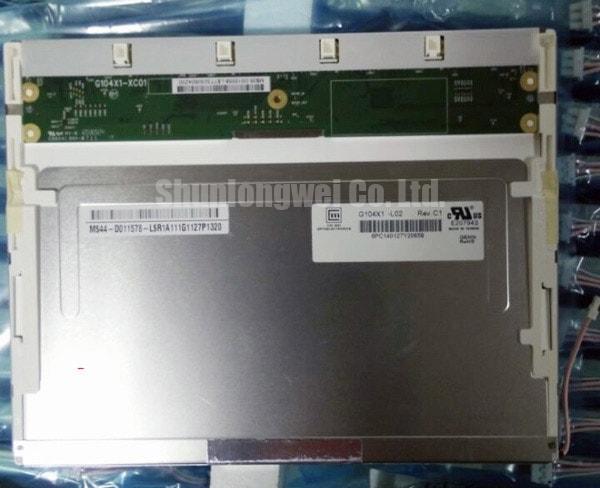
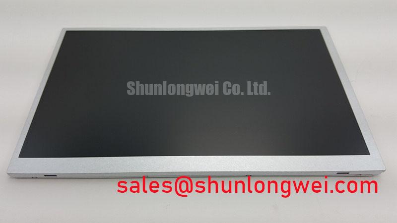
Before fitting the G104X1-L03, inspect the display module perimeter, mounting points, signal connector, and cable restraint path under clean bench lighting, then compare every interface and supply requirement with the original equipment documentation. This AUO unit is identified as an Industrial Grade LCD/HMI Panel in a TFT-LCD Display Module construction.
For repair work, the model code must be treated as the primary identity reference, but it does not replace a complete interface check. Confirm the original panel label, mechanical envelope, connector orientation, controller board configuration, and backlight drive arrangement before power is applied. The system integrator should verify the required supply voltage, timing standard, signal mapping, and backlight requirements from the original panel documentation.
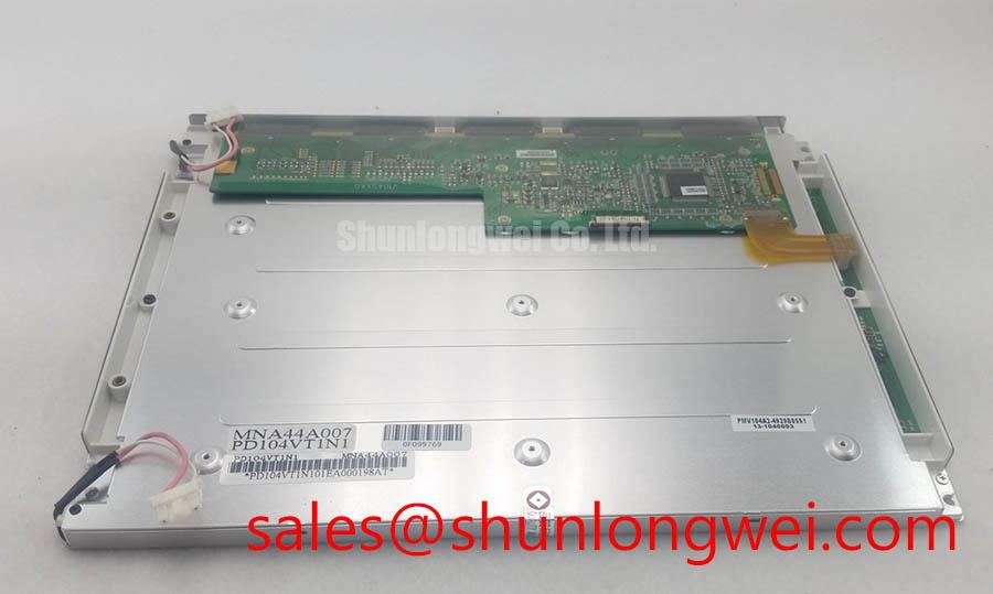
Where a same-size industrial display is being evaluated during equipment restoration, G104VN01 V1 can be reviewed as a separate reference model. It should not be treated as a direct replacement without confirming mechanical fit, electrical interface, display timing, optical behavior, and firmware compatibility in the host equipment.
Start optical assessment with the existing panel energized in its original equipment, if safe test conditions are available. Compare the screen at minimum and maximum operator-selected brightness, inspect for uneven illumination, and note whether brightness changes smoothly or in visible steps. A dim image can originate in the backlight assembly, its power circuit, a control signal path, the host controller, or optical aging. It should not be assigned to one cause without measurement.
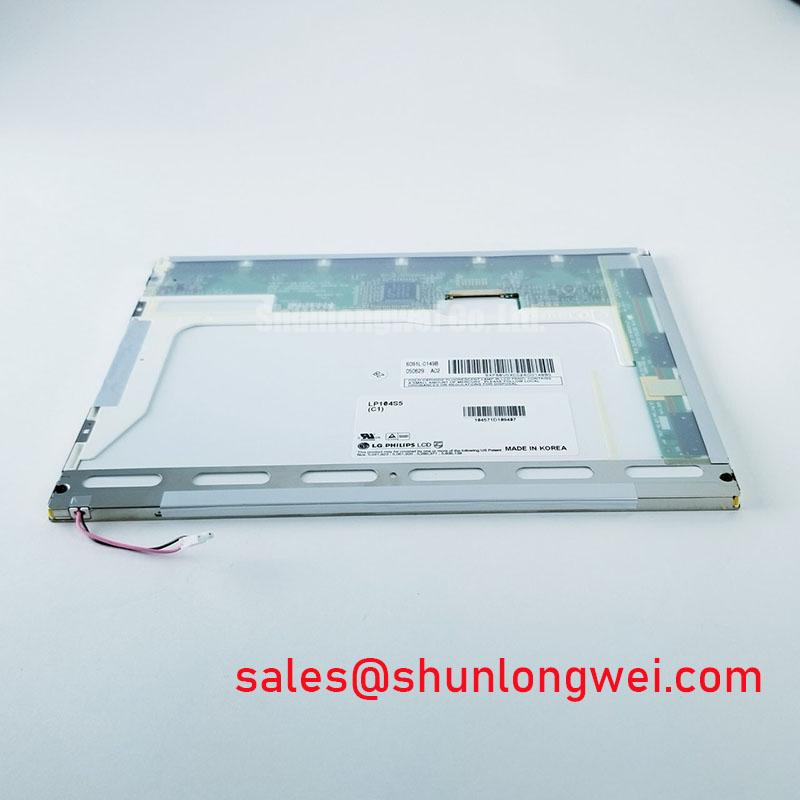
For the G104X1-L03, the installed backlight technology and its electrical requirements must be verified from the original AUO documentation and the equipment wiring. A conversion between a high-voltage lamp backlight arrangement and a constant-current LED arrangement is a system modification, not an automatic panel service procedure. Such a project requires review of mechanical clearances, heat distribution, dimming control polarity, driver protection behavior, display optical stack compatibility, and serviceability after installation.
Design Consideration: an LED retrofit can alter the controller’s expected dimming behavior even when the panel appears mechanically compatible. The host board may provide an enable signal, a brightness command, or a PWM control waveform that requires conditioning or interpretation by the replacement driver. Engineers should capture these signals from a known-good machine, review their timing during startup and shutdown, and validate brightness stability through the full operating range.
Do not use a stated lamp ignition voltage, LED operating current, PWM ratio, acoustic-noise target, or lifetime figure as a requirement for this model unless it appears in the applicable factory documentation. Backlight service decisions should be based on measured driver output, validated connector pin assignment, and the specification of the actual assembly being repaired.
Signal integrity remains relevant whenever a display interface board is repaired or replaced. Clock stability, data alignment, and hold-time margin are controlled by the host transmitter, cable assembly, connector condition, and receiver requirements. During temperature-related troubleshooting, compare the display signal with a known-good path using suitable instrumentation. Intermittent image corruption after warm-up or cold start may indicate a timing-margin issue, cable degradation, connector contact condition, or a fault elsewhere in the display chain.
⚠️ Maintenance Note: Disconnect system power and allow stored energy in the display power circuitry to discharge before handling panel or backlight connectors.
Flashlight Dark-Shadow Optical Diagnostic to Isolate Logic vs. Backlight Failure Modes
A controlled visual test helps separate an image-generation issue from an illumination issue without forcing a premature repair decision. First, allow the machine or bench controller to complete its normal display startup. Second, present stable red, green, blue, black, and white test images from the approved service source where available. Third, inspect the image directly and then repeat the inspection with a flashlight held at an oblique angle across the dark screen surface.
If faint image structure becomes visible under external light while the normal backlight appears absent, the observation can support further investigation of the illumination path. It does not by itself prove that the backlight source is defective. Verify the backlight enable command, driver input supply, control wiring, protective shutdown behavior, and all connector seating before replacing parts.
A persistent narrow line, localized color shift, or image area that changes when the module is gently supported may require investigation of the panel, the flex connection, the host cable, or mechanical stress around the mounted assembly. Avoid pressing on the active display area to force a symptom. Applied point pressure can create additional cosmetic or functional damage and can obscure the original fault pattern.
Engineering Recommendation: record the screen condition with the same test pattern at room temperature and after the equipment has reached its normal enclosure temperature. This comparison gives the repair team a repeatable reference and reduces reliance on memory when evaluating intermittent defects. It is particularly useful when a panel appears normal at the bench but develops artifacts after installation.
Inspect the signal connector under magnification for incomplete latch engagement, foreign material, cable strain, or damage to the cable retention feature. Refit the cable using the host equipment’s approved service method. The correct connection standard for the G104X1-L03 must be verified from original documentation rather than inferred from connector appearance.
For broader fault-isolation methods covering panel interfaces, backlight behavior, display artifacts, and integration checks, consult The Ultimate Guide to Industrial TFT LCD Technology. Use the guidance alongside the original equipment schematic and the applicable panel documentation.
Thermal Cycling Degradation of Polarizer Adhesives & Sealant Gasket Integrity
Thermal cycling checks should begin with the display mounting system rather than the active screen. Examine the bezel contact line, any external gasket, mounting brackets, fasteners, cable clamps, and enclosure drainage path. A panel can show acceptable electrical behavior while uneven clamping load, a displaced sealing surface, or cable pull transfers stress into the display assembly.
Low-temperature operation can make liquid crystal response appear slower, while repeated hot and cold transitions can expose weaknesses in surrounding mounting materials and enclosure seals. These are system-level conditions, not confirmed operating ratings for the G104X1-L03. The permitted temperature range, storage limits, humidity conditions, and condensation restrictions must be taken from the applicable AUO factory documentation.
Design Consideration: distribute mounting force evenly through the equipment’s intended mounting features and avoid forcing the module into a distorted bezel opening. Uneven support can contribute to pressure marks, localized brightness variation, or intermittent connection stress. The equipment manufacturer’s mechanical drawing and fastening requirements should govern the assembly process.
In cabinets and operator stations exposed to seasonal temperature swings, inspect for condensation marks, dust tracks near gasket interfaces, and corrosion around the display connector or controller board. Correcting enclosure airflow, cabinet sealing, and cable routing may be necessary before a replacement panel is installed. Replacing the display alone will not resolve an ongoing moisture or mechanical-stress condition.
Where dimming is controlled by the host system, evaluate the observed brightness behavior at the actual operating temperature. Visual flicker, brightness instability, or audible driver noise can arise from the controller, dimming command, cable coupling, power integrity, or the backlight driver. The system engineer should verify the control waveform and the driver requirements rather than imposing a generic PWM frequency or duty-cycle setting.
For a potential heavy earthmoving or telematics-display installation, environmental suitability should be reviewed as a compatibility assessment. Confirm enclosure sealing, vibration isolation, power quality, operator viewing position, service access, and the panel’s documented environmental limits before selecting or installing the module.
Surface Anti-Glare & Anti-Reflective Etched Coating for High Ambient Readability
Assess screen readability with the panel installed at its actual viewing angle and under representative ambient light. Reflections from windows, cabin glass, work lights, or adjacent indicators can be mistaken for low backlight output. Clean the outer display surface using a method approved for the equipment, then compare the image in shaded and high-ambient conditions before judging optical performance.
The surface treatment, viewing characteristics, contrast behavior, and optical ratings of the G104X1-L03 must be confirmed from the official AUO documentation. Do not assume that an industrial TFT-LCD module has anti-glare etching, anti-reflective treatment, a particular viewing cone, or a specific display mode solely from the model family or its use in similar equipment.
Engineering Recommendation: preserve the original bezel geometry and any protective window arrangement where these parts are part of the equipment’s optical design. An added cover lens, unsuitable adhesive, contaminated protective film, or an altered air gap can introduce glare, haze, color shift, or apparent nonuniformity. Verify readability after final assembly rather than only with the bare module on a bench.
In high-electromagnetic-noise industrial equipment, route the display cable according to the original harness design, maintain its intended retention points, and keep it away from unshielded noise sources where the equipment layout permits. Differential interface performance depends on the complete signal path, including the transmitter, cable, connector, return path, grounding arrangement, and receiver. Any impedance or timing target must be derived from the documented interface requirements and validated by system testing.
A display that remains readable but shows occasional image disturbance during motor starts, radio transmission, or hydraulic actuation should be investigated with the host equipment’s power and signal behavior in view. Check grounding continuity, connector retention, cable shielding arrangement where fitted, and the timing of the disturbance relative to machine events. This approach supports evidence-based repair without assigning a single cause to a complex field symptom.