

Content last revised on November 5, 2026
Backlight Inverter Striking Voltage & Ignition Debugging
Trace the backlight connections to the installed driver before applying power to the removed display assembly. Design Consideration: The inverter topology must be established from the equipment circuit and panel connection requirements; this heading does not identify the G104X1-L04 backlight as a dual-channel CCFL assembly. CCFL ignition measurements and constant-current LED measurements require different instruments, connections, and interpretation.
For an equipment assembly containing a CCFL inverter, a qualified technician should observe startup with an appropriately rated high-voltage probe and compare the behavior of the lamp channels. A brief flash followed by shutdown can involve the lamp circuit, connector insulation, feedback path, or protection circuitry. Check those paths against the inverter schematic rather than repeatedly restarting the display or bypassing protection. Audible buzz should be investigated alongside dimming commands, transformer mounting, and mechanical resonance.
In an LED backlight circuit, evaluate current regulation, enable timing, dimming response, and the driver's open-circuit or short-circuit fault indication. Engineering Recommendation: Select any dimming adjustments through measured brightness stability, acoustic behavior, and driver limitations. A numerical PWM frequency, dimming ratio, or service-life claim cannot be transferred between backlight technologies.
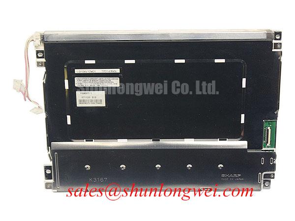
The TCG121XGLPCPNN-AN70 provides another display assembly for separate system evaluation. Its backlight connections and driver requirements must be assessed independently; its product designation does not establish a compatible driver for the G104X1-L04.
Aluminum Heat Spreader Sizing & Thermal Interface Placement along Narrow Display Edges
Map enclosure temperatures around the display edges before adding heat spreader rails or changing thermal interface placement. Design Consideration: A proposed aluminum rail should transfer heat through an approved structural contact area while preserving connector access, mounting clearance, and electrical separation. Rail dimensions depend on measured heat flow and enclosure conditions, rather than the width of an exposed display edge alone.
Keep thermal pads and gasket compression from imposing concentrated loads on the display frame. Uneven fastening or an overcompressed seal can distort the assembly and produce pressure-related brightness nonuniformity. Tighten the mounting arrangement progressively using the applicable assembly specification, then inspect uniform light and dark images with the bezel fitted. Compare the image before and after fastening to identify installation-sensitive changes.
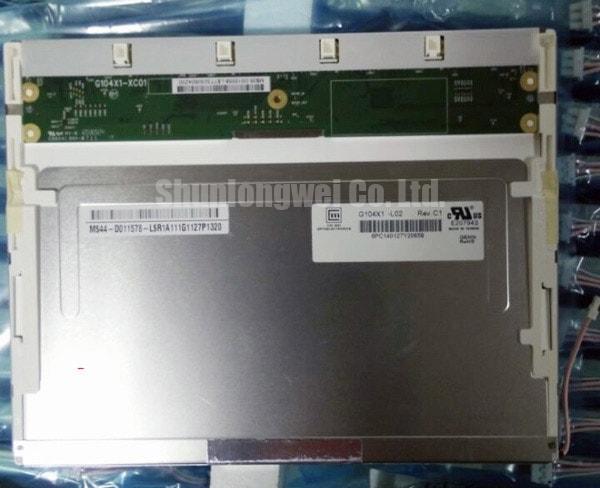
The following comparison separates established product identity from the interfaces that control replacement suitability. It does not assign equivalence between the panels.
| Assessment item | G104X1-L04 | NL6448BC33-71 |
|---|---|---|
| Product identity | AUO industrial LCD/HMI panel, as specified in the supplied product information | Separate display model for comparison |
| Module construction | TFT-LCD active matrix color display module | Consult datasheet |
| Size, resolution, mounting dimensions | Consult datasheet | Consult datasheet |
| Supply, signal interface, backlight connections | Consult datasheet | Consult datasheet |
| Optical and environmental limits | Consult datasheet | Consult datasheet |
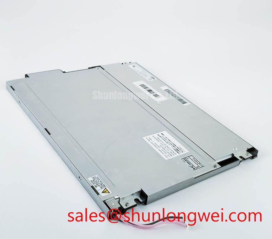
When comparing the NL6448BC33-71, resolve these interface differences before changing brackets or ordering a harness. For a precision electronic test and measurement instrument, compatibility assessment should also include enclosure depth, visible image position, and controller output timing.
Cold conditions can slow liquid-crystal transitions, while condensation can affect exposed connections and optical surfaces. Any enclosure heater should be evaluated against the panel's permitted operating conditions and local temperature distribution. Maintenance Note: Inspect ventilation paths and gasket seating periodically, and allow condensation to clear before energizing the display.
Surface Anti-Glare (AG) & Anti-Reflective (AR) Etched Coating for High Ambient Readability
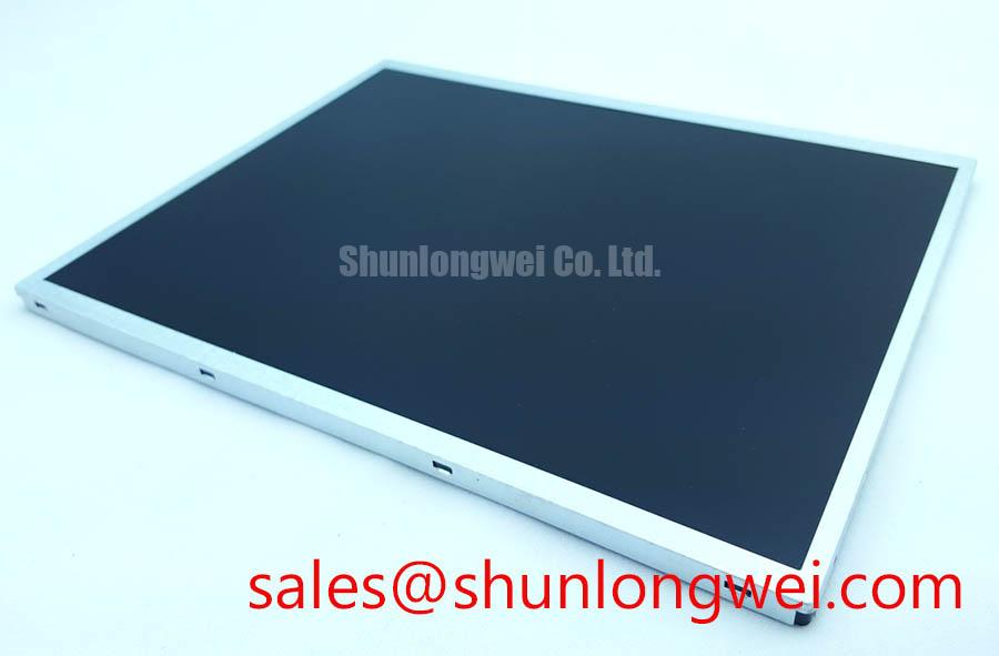
Inspect the assembled display under the actual ambient lighting and operator viewing direction before specifying an additional optical surface. Design Consideration: Anti-glare treatment redistributes reflected light, whereas anti-reflective treatment reduces reflection through its optical construction. Neither treatment should be attributed to the G104X1-L04 without a matching surface specification, and an etched finish should not be assumed from appearance.
Check fine text, low-contrast indicators, and dark backgrounds through the installed cover window. Surface haze, cover reflections, contamination, and viewing direction can each reduce readability. Observe grayscale patterns from the intended working position rather than assigning TN, IPS, or MVA behavior to this panel without its electro-optical specification.
The Winstar Industrial TFT-LCD and OLED Display Modules and Tianma NLT Industrial TFT-LCD Display Technologies resources provide broader display technology context. Their product specifications should remain separate from the ratings of this model.
If the host assembly includes touch input, evaluate that subsystem separately from LCD image quality. Glove response, moisture rejection, and touch accuracy depend on the installed sensor, controller, cover construction, and configuration. Cold image persistence and missed touch events require separate observations; changing backlight brightness will not establish their cause.
Eye-Diagram Voltage Margin & Differential Noise Floor Verification in High-Vibration Bays
Identify the signal interface and connector assignment before attaching probes or modifying cable shielding. Engineering Recommendation: For a confirmed differential interface, inspect signal quality at the receiver with a suitable differential probe and account for probe loading. For a parallel interface, evaluate clock-to-data relationships against the receiving device's timing requirements.
Compare operation with nearby switching equipment inactive and active while keeping the display pattern and cable position consistent. Pixel instability or horizontal bands can involve supply disturbance, signal integrity, connector movement, or controller timing. Correlating these conditions with measured waveforms is more useful than assigning a single cause from the image alone.
Shield termination, chassis bonding, and any common-mode suppression component should follow the equipment's grounding design. Evaluate changes for both interference reduction and signal degradation; adding a ferrite or altering a shield connection does not establish EMC compliance. The distributor's Industrial Display & HMI Solutions engineering guide provides related integration context for enclosure and interconnection assessment.
Under vibration, inspect connector retention and cable strain relief without transferring harness loads into the panel. After reassembly, verify image stability, power sequencing, and controller timing through the equipment's specified operating conditions. Record the final harness routing and fastening arrangement so subsequent maintenance can reproduce the tested installation.