

Content last revised on September 27, 2026
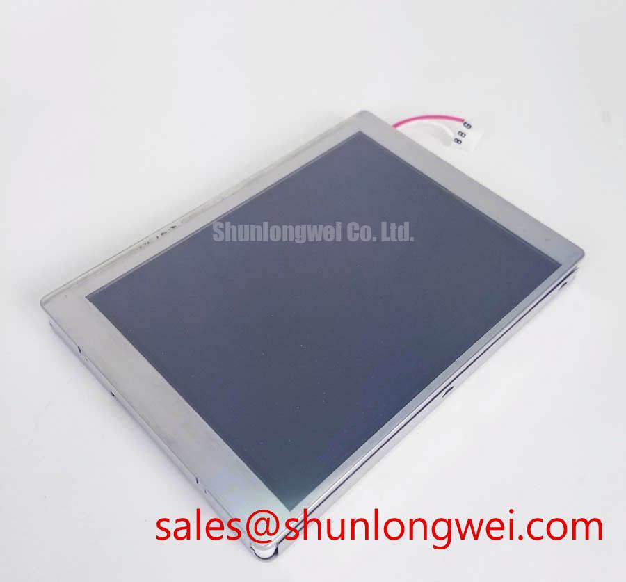
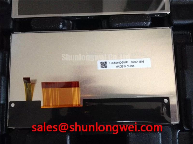
LQ058Y5DG01 Sharp TFT LCD Industrial Display Module
Start the service check by isolating power, inspecting the display connector and FFC seating, and comparing the replacement unit with the original panel label before applying any signal or backlight power. The LQ058Y5DG01 is a Sharp Industrial Grade LCD/HMI Panel supplied as a TFT LCD Display Module.
This product page focuses on practical replacement and integration checks for industrial HMI equipment, including possible evaluation in railway passenger information systems and cab signalling displays. The available product information identifies the product category, manufacturer and module construction, but does not confirm the electrical interface, display resolution, supply voltage, backlight architecture, connector pinout or operating temperature range. Those values must be checked against the original Sharp documentation and the equipment service manual before installation.
| Model | LQ058Y5DG01 |
| Manufacturer | Sharp |
| Product category | Industrial Grade LCD/HMI Panel |
| Construction | TFT LCD Display Module |
Suppressing Pixel Jitter and Horizontal White Lines Induced by Adjacent 400V Motor Drives
When a replacement display is installed close to variable frequency motor equipment, begin with the signal path rather than changing the panel. Observe the image during motor acceleration, deceleration and steady operation, then compare the display behavior with the drive disabled. Pixel jitter, intermittent horizontal bands or unstable synchronization can involve cable routing, reference potential differences, connector contact, shielding or signal integrity. These symptoms should not be assigned to the LQ058Y5DG01 without checking the complete display chain.
The display cable should follow a controlled route away from motor output conductors, braking resistors and switching nodes. Where the equipment design uses a shielded FFC, LVDS cable or another differential display connection, the system integrator should confirm the original cable construction, shield termination and connector pin assignment. A 360 degree shield termination can be considered where it is compatible with the equipment enclosure and connector design, but the termination method remains a system level decision. A pigtail connection, floating shield or shield bonded at an unsuitable point can increase common mode coupling rather than reduce it.
Differential pairs require a continuous reference path and consistent geometry. A commonly used design consideration for LVDS routing is approximately 100 Ω differential impedance with a tolerance near ±10 percent, but this is not an official LQ058Y5DG01 specification and must not be treated as a confirmed requirement for this model. The equipment designer should verify the original transmitter, receiver and cable documentation. Pair skew should also be checked against the actual interface specification and receiver tolerance.
Ferrite suppression can be evaluated when conducted common mode noise is visible on the display link. The selected ferrite must be assessed across the switching noise spectrum, and its effect should be verified with a known good panel and an oscilloscope. Installing a ferrite without checking the signal bandwidth may alter edge quality or create a new intermittent fault. For a replacement comparison, use the same cable, grounding arrangement and drive operating state so that the panel is not being evaluated alongside an unverified wiring change.
For system planners comparing industrial display paths, LM64P10 may be reviewed as a separate reference model. It should not be treated as a drop in replacement unless mechanical dimensions, optical requirements, electrical interface, mounting features and software timing are confirmed by the integrator.
⚠️ Field Alert: Disconnect equipment power and allow stored energy to discharge before inserting or removing the display cable, because live connector handling can expose signal contacts to unintended electrical stress.
Backlight Architecture and Ignition Debugging
Backlight troubleshooting must begin by identifying the architecture fitted to the actual equipment. The available product information confirms a TFT LCD Display Module, but it does not confirm CCFL tube count, inverter topology, LED configuration, ignition voltage, dimming method or backlight connector assignment. The system integrator should verify the required backlight supply and control signals from the original panel documentation rather than assuming that a CCFL inverter or constant current LED driver is suitable.
For a panel removed from service equipment, inspect the backlight connector, cable insulation, inverter area and control wiring before applying power. A dark screen with visible image content can point the investigation toward the backlight chain, while a completely blank screen requires separate checks of the display supply, timing source and signal path. These observations help narrow the test area but do not establish a single failed component.
Some legacy industrial displays use resonant CCFL inverter circuits that can generate hazardous high voltage during ignition. Ignition voltage must be checked against the documentation for the specific lamp and inverter assembly; it is not a confirmed parameter for LQ058Y5DG01. Measurements should be performed with equipment rated for the circuit and by personnel qualified to work on high voltage systems. Acoustic buzz may arise from inverter magnetics, mechanical vibration, lamp operation or mounting resonance, so the inverter assembly and mechanical support should be inspected together.
Other display assemblies use constant current LED drivers with PWM or analog brightness control. A 1000:1 dimming ratio is not an official parameter supplied for this model and should not be assumed. If the service assembly uses LED backlighting, verify the driver current, enable threshold, dimming polarity, PWM frequency and connector assignment from the relevant documentation. A driver that fits mechanically may still be electrically incompatible.
Cold operation can lengthen visible response time and alter the startup behavior of the display system. Liquid crystal viscosity, lamp ignition behavior, cable flexibility and power supply sequencing can all influence the first image after power up. For equipment exposed to sub zero conditions, designers should reproduce the actual enclosure temperature and startup sequence, then check image formation, brightness stability and control response. A heater strip or enclosure heater should only be controlled according to the equipment thermal design; its use cannot be inferred from the LQ058Y5DG01 model number.
The LMS700KF01-001 can be examined as a separate display solution when reviewing a broader display architecture. It is not presented as a guaranteed companion or substitute for LQ058Y5DG01. Connector compatibility, backlight control and mechanical fit require direct confirmation.
Micro Twist Mechanical Stress and Glass Substrate Driver Fault Isolation
Mechanical inspection is essential when a display has been exposed to vibration, repeated cabinet access or uneven bezel pressure. Check the glass edge, frame, connector area and flexible cable path under controlled lighting. Do not press the active area to reproduce a fault. A changing image caused by light contact can indicate a mechanical or connection issue, but it does not identify a particular internal failure mechanism.
A practical bench sequence is to verify the primary colors red, green and blue, followed by a white field and a dark field. Observe the panel from the normal viewing position and from an oblique angle. A flashlight held at approximately 45 degrees can help reveal a faint image when the backlight is absent, but this is a qualitative diagnostic method rather than a factory acceptance test. If a faint image is present, compare the backlight circuit and enable path before drawing conclusions about the LCD glass or driver area.
Vertical lines, horizontal lines, localized dark regions and intermittent image sections should be documented with photographs taken at the same operating condition. Then inspect the cable lock, connector seating and chassis pressure. A cable that is sharply bent near its termination may have an unstable contact path, while a display frame installed under uneven compression can place unwanted stress on the glass assembly. The correct repair action depends on whether the symptom follows the panel, cable, controller or mechanical installation.
FPC and FFC routing should preserve the bend condition specified by the original equipment design. Avoid folding the cable directly over a sharp chassis edge, trapping it beneath a bracket or allowing vibration to pull on the connector. Strain relief should be provided by the equipment structure rather than by the connector contacts. The integrator should verify locking force, insertion direction and mating depth from the connector documentation.
For a high EMI installation, differential pair routing should maintain a continuous reference path and avoid unnecessary transitions. The often used 100 Ω ±10 percent LVDS design value is an engineering consideration for applicable interfaces, not confirmed LQ058Y5DG01 factory data. The actual panel interface must be identified before this value is used in a board or cable review.
Thermal Cycling Degradation of Polarizer Adhesives and Sealant Gasket Integrity
Thermal evaluation should reproduce the equipment enclosure rather than relying only on the nominal ambient temperature near the cabinet. Measure the temperature at the display mounting area, inspect changes in image response during startup and watch for edge lifting, haze, uneven brightness or intermittent lines after cycling. The available product information does not specify a temperature range, polarizer construction, adhesive type or perimeter sealant rating for LQ058Y5DG01, so those characteristics must be confirmed through the applicable Sharp documentation.
At low temperature, slower liquid crystal response can make moving text and gray transitions appear delayed. This can be especially noticeable in cab signalling displays and passenger information terminals where status changes are viewed immediately after power application. The system designer should evaluate the actual refresh timing, image content and controller settings at the intended operating condition. Any response time value used for acceptance must come from the panel documentation or a controlled measurement procedure.
At elevated temperature, inspect the bezel interface and display perimeter for signs of enclosure pressure, contamination or moisture ingress. The panel should be mounted so that the frame is supported evenly without twisting the glass. If the enclosure uses a gasket, confirm that its compression and material are defined by the equipment design. Do not infer gasket integrity or adhesive lifetime from the TFT category alone.
Brightness control also requires interface verification. A PWM frequency between 200 Hz and 1 kHz is a possible system design range for some industrial backlight controllers, but it is not a confirmed specification for this Sharp module. The correct value depends on the backlight driver, camera exposure requirements, visual flicker limits and control electronics. Designers should verify duty cycle linearity, enable timing and dimming polarity with the installed driver while checking for audible behavior and visible modulation.
When this panel is evaluated for a railway passenger information system or cab signalling display, the full installation should be tested with its real mounting frame, cable restraints, controller, backlight supply and enclosure airflow. A useful technical reference for broader panel selection and integration principles is The Ultimate Guide to Industrial TFT LCD Technology. The reference does not replace the model specific Sharp documentation required for electrical and environmental approval.