
Content last revised on September 24, 2026
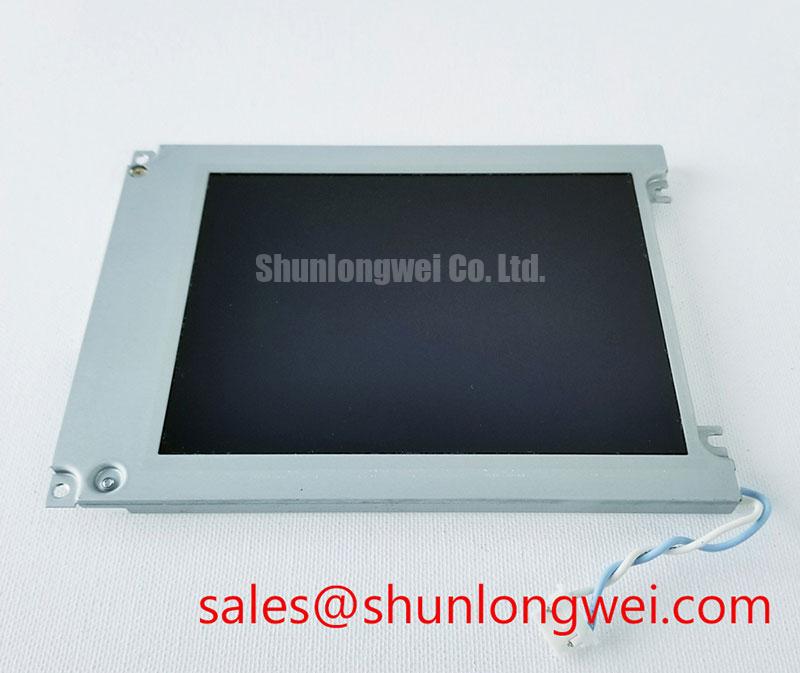
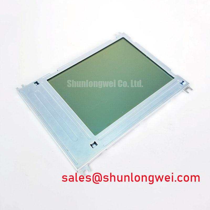
KG057QV1EA-G020 Kyocera TFT-LCD Display Module for Industrial HMI
Before installation, compare the replacement panel with the removed unit, inspect the connector and bezel area, and verify the original equipment documentation for electrical, optical, and mechanical compatibility. The KG057QV1EA-G020 is a Kyocera Industrial Grade LCD/HMI Panel supplied as a TFT-LCD Display Module. The supplied product information identifies the model and manufacturer but does not provide a complete factory specification set.
| Manufacturer | Kyocera |
| Model | KG057QV1EA-G020 |
| Product category | Industrial Grade LCD/HMI Panel |
| Package or housing | TFT-LCD Display Module |
| Specification status | Basic product identification provided; verify detailed specifications |
The supplied information does not confirm the panel supply voltage, interface pinout, resolution, brightness, viewing angle, backlight electrical data, or mounting dimensions. The system integrator should verify each required value from the original panel documentation and the equipment service manual before applying power. For procurement reference, the product page is available at KG057QV1EA-G020 product information.
Suppressing Localized Thermal Gradients to Prevent Chronic Optical Yellowing
When this display is evaluated for an industrial HMI, radar monitor, or navigation bridge console, inspect the enclosure around the active area for localized heat sources. Power converters, processors, sunlight-heated metalwork, and restricted airflow can create temperature differences across the display perimeter. A suitable heat-spreader arrangement is a system-level design consideration rather than a confirmed specification of the Kyocera module. The mechanical designer should distribute heat without placing pressure on the panel frame or blocking the required backlight path.
Clock and data integrity also require confirmation at the host interface. Determine whether the original system uses LVDS, TTL, or another display interface, then verify transmitter timing, data hold requirements, connector orientation, and cable routing against the original documentation. Do not assume a JEIDA or VESA mapping from the model number alone. The controller, cable, and receiver must be assessed together across the intended operating temperature range.
Kyocera’s industrial display information can provide useful manufacturer context for optical and display technology evaluation; it should not replace the exact product documentation for this model. See Kyocera Industrial TFT-LCD Display Technologies.
Full-Screen Primary Color AOI Screening for Stuck Sub-Pixels and Uniformity
Incoming inspection should begin with a clean, powered test fixture using the same controller and signal format as the target equipment. Display full-screen red, green, blue, black, and white fields, recording any persistent point defects, line artifacts, uneven luminance, or intermittent regions. A low-angle flashlight inspection with the screen unpowered can help reveal surface contamination, frame distortion, or localized shadowing, but it cannot by itself identify a driver or backlight fault.
If a line defect appears, compare the panel with a known-good signal path and inspect the cable seating, shielding, ground reference, and connector retention. An oscilloscope may help determine whether the observed behavior is associated with signal integrity or with the display assembly, but the result should be interpreted against the original interface specification. Differential-pair impedance, skew, and termination values are design considerations for the complete cable and controller path, not published factory parameters for this module in the supplied data.
💡 Pro Tip: Keep high-speed display pairs routed together with controlled reference continuity and avoid sharp routing changes near the panel connector.
Preventing Localized Light Guide Plate Compression Warp on Dark Screen Fields
Before fastening the display into a replacement bezel, confirm the opening envelope, corner clearances, connector relief, and the position of every support point. Uneven frame pressure can produce optical non-uniformity or mechanical stress that becomes visible on dark test fields. Because the supplied factory data does not state bezel tolerances, light-guide construction, or fastening torque, those values must come from the original equipment drawing or Kyocera installation documentation.
Use a cross-pattern tightening sequence only when the equipment design calls for multiple fasteners, and allow the display frame to seat naturally before final inspection. Do not use the bezel to compensate for a misaligned chassis. Check the assembled unit with black and low-level gray images, then compare it with the uninstalled panel to separate enclosure-induced effects from panel behavior.
For a broader explanation of display selection, interface considerations, and common integration errors, consult The Ultimate Guide to Industrial TFT-LCD Display Technology.
Wide-Temperature Operational Margin and Sub-Zero Liquid Crystal Response
The supplied product data does not confirm an operating temperature range, contrast ratio, anti-glare treatment, gray-to-gray response, or sealing construction for the KG057QV1EA-G020. These parameters should therefore be verified before selecting the module for an exposed marine radar or navigation bridge console. Direct sunlight, salt-laden air, condensation, and enclosure heating require assessment at the system level, including sealing, ventilation, optical cover design, and service access.
For cold-start evaluation, allow the complete display assembly to stabilize at the intended environmental condition, then check image uniformity, startup behavior, grayscale transitions, and interface stability. Increased liquid-crystal viscosity can affect response behavior at low temperature, but the observed result depends on the panel construction, drive timing, and controller configuration. Record measurements against the approved equipment limits rather than applying generic display assumptions.
⚡ Safety Interlock Note: Disconnect power before removing or inserting the display cable, and verify the connector keying before reassembly.
Potential use in a harsh marine radar or navigation bridge console remains a compatibility assessment only; enclosure sealing, optical performance, interface timing, and mechanical fit must be validated by the system designer.