Content last revised on October 20, 2026
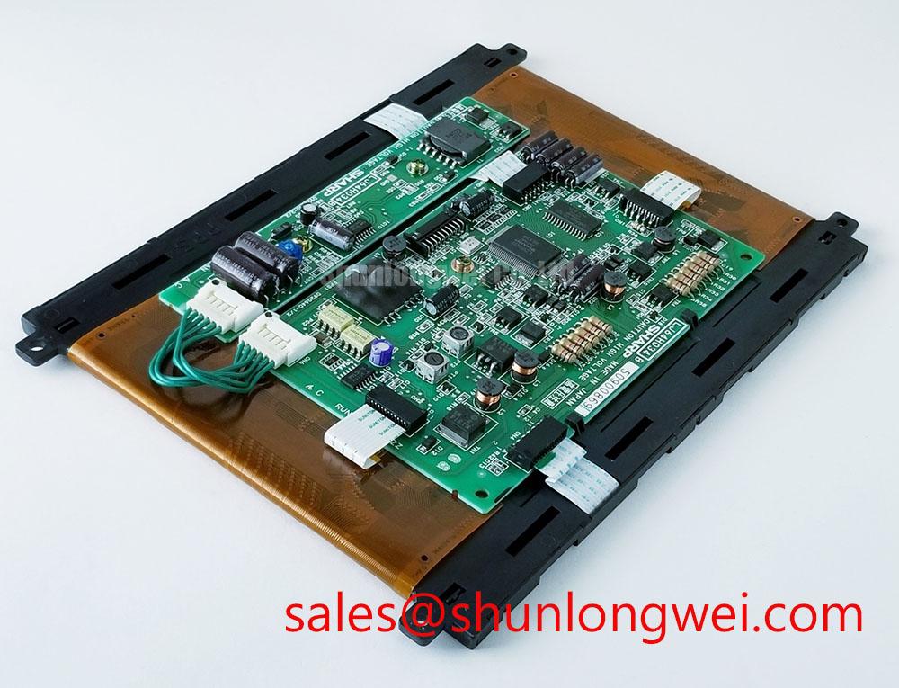
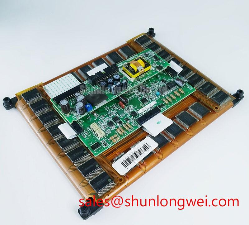
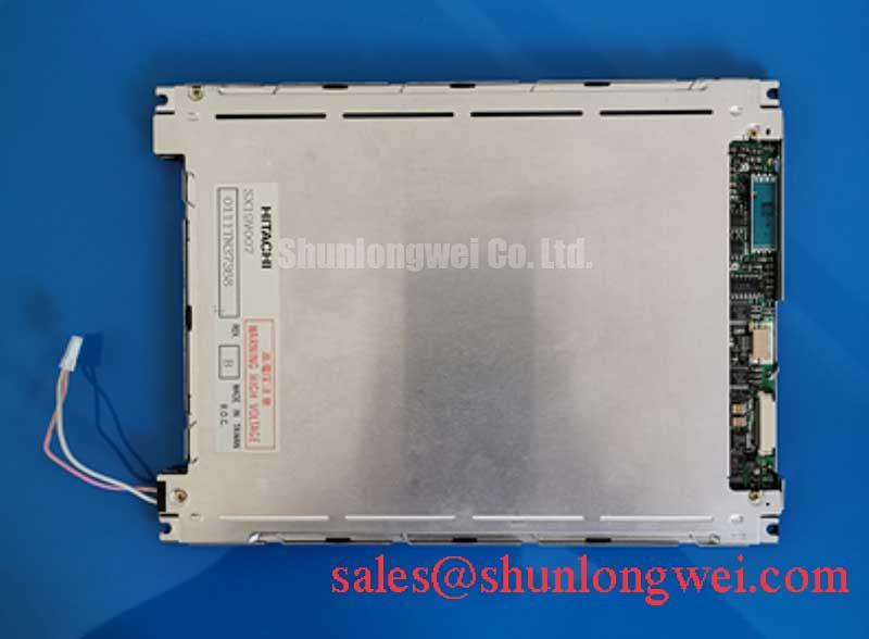
During a CNC operator panel or robot teach pendant fault check, isolate the display assembly, inspect the bezel and cable seating, and compare the replacement identification before applying power. The documented product category for LQ070M1SX01 is an Industrial Grade LCD/HMI Panel from Sharp, packaged as a TFT LCD active matrix color display module. Its listing status is a decoded baseline standard form factor, so mechanical clearance, connector orientation, signal mapping, and backlight arrangement must be matched with the original equipment before installation.
For maintenance teams, this unit is best assessed as a display module within a larger HMI signal and power chain. The display itself should not be assigned an unverified supply voltage, interface pinout, backlight type, brightness rating, viewing angle, or lifetime figure. The system integrator should verify those values against the original panel documentation and the equipment wiring before energizing the assembly. This approach is especially important when replacing a panel inside a CNC operator console or a robot hand-held teach pendant, where cable routing and enclosure pressure can affect long-term reliability.
Suppressing Acoustic Capacitor Buzz and EMI Emissions across 200 Hz to 1 kHz PWM Frequencies
When audible noise appears during display dimming, first separate the panel signal path from the backlight power path. A switching backlight driver, its input filtering, mounting surface, and cable loop can all contribute to acoustic vibration or conducted noise. The documented information for LQ070M1SX01 does not establish a specific backlight topology, so the installed equipment should be inspected before applying assumptions about a high-voltage CCFL inverter or a constant-current LED driver.
For a system using a high-voltage lamp inverter, cold-start behavior should be evaluated with an appropriately rated differential probe and isolation procedure. The 1500 to 1650 Vrms ignition range mentioned for some CCFL systems is a design reference for the external inverter path, not an official rating of this Sharp display module. For an LED driver, the relevant checks are current regulation, PWM edge quality, dimming linearity, and conducted noise on the supply return. A 1000:1 dimming ratio may be used as a driver-level design target only when the complete backlight assembly supports it.
During the 200 Hz to 1 kHz test band, listen for changes in enclosure resonance while observing the backlight waveform and display uniformity. Keep the high-current switching loop physically separate from LVDS wiring, and return shield or chassis connections according to the equipment grounding design. The transmitter clock should be checked for jitter and data hold margin across the specified operating temperature range of the host system. These are Design Considerations for the surrounding electronics rather than factory specifications assigned to LQ070M1SX01.
For a related display comparison, engineers can review LQ057Q3DC03 as a same-family reference point, while retaining the original connector, optical, and mechanical requirements as the controlling criteria.
20-Pin or 30-Pin Differential LVDS Timing, Pixel Clock and Skew Compensation
Split-screen images, unstable colors, or intermittent vertical regions require a signal-path comparison rather than an immediate panel replacement. Confirm the installed connector count, pin numbering, ground returns, pair assignment, and transmitter mapping from the original equipment documentation. LQ070M1SX01 is identified as a TFT LCD active matrix color module, but the supplied baseline data does not define a 20-pin or 30-pin LVDS interface, logic supply voltage, JEIDA or VESA mapping, or pixel clock limit.
The power sequence should be observed at the panel connector with the signal enable and reset behavior recorded. The stated 0.5 ms to 10 ms rise-time window can serve as an engineering reference for a compatible host design only when confirmed against the applicable panel documentation. It should not be treated as an official LQ070M1SX01 specification. A controlled rise, stable ground reference, and correct enable order help distinguish a timing fault from a damaged cable or connector contact.
For differential routing, a 100 ohm characteristic impedance is a common Design Consideration for LVDS pairs. Route each pair together, avoid unnecessary stubs, and keep pair lengths consistent through the connector transition. Where a known-good panel or signal source is available, compare the eye opening and pair timing at the panel end. A split image can result from mapping errors, pair reversal, skew, insufficient signal amplitude, or connector contact problems, so the observed waveform should be compared with the working path before changing the module.
Cold environments can lengthen liquid crystal response and make grey-to-grey transitions appear slower. If the host enclosure includes a heater or controlled warm-up sequence, its use should be evaluated as part of the complete equipment design rather than assumed to be an accessory supplied with this display. The same principle applies to static HMI screens: use the equipment’s display management functions where available to reduce prolonged fixed imagery and inspect for residual image behavior during scheduled maintenance.
High-Nits Edge-Lit LED Rail Thermal Dissipation and Light Guide Preservation
Thermal inspection should focus on the narrow edges of the display and the surrounding mounting frame, where a driver or light source can create a localized hot area. The supplied product data does not confirm an edge-lit LED architecture, PMMA light guide construction, high-nits rating, L70 value, or B50 lifetime for LQ070M1SX01. These properties must therefore be established from the original assembly documentation instead of being inferred from the model designation.
As a Design Consideration for compatible equipment, an aluminum spreader or frame should make even contact with the intended thermal path without pressing on the active viewing area. Uneven fastener loading can distort the bezel or create localized optical non-uniformity. The mounting interface should release mechanical stress uniformly, and sealing materials should be positioned so that they do not intrude into the optical aperture or interfere with cable bending.
PWM testing should examine brightness linearity, visible flicker, acoustic response, and driver temperature across the intended operating range. The 200 Hz to 1 kHz range is a practical external driver test band, not a confirmed specification of this module. If the equipment is used for long periods with bright static text, schedule display content changes or a controlled screen saver where the host system permits it. This reduces the need to interpret persistent image retention as an immediate panel failure.
In a broader display power topology, the related LQ065T5AR05 can be reviewed as a separate display solution reference. It should not be treated as a direct substitute without checking electrical, optical, mechanical, and interface compatibility.
Surface Anti-Glare and Anti-Reflective Coating for High Ambient Readability
Readability testing should be performed at the actual operator position, with the enclosure, ambient lighting, protective window, and viewing direction installed as they will be in service. The supplied specifications do not confirm an AG etched surface, AR coating, TN, IPS, or MVA liquid crystal mode for LQ070M1SX01. The display technology should therefore be identified from the applicable panel documentation before making a viewing-angle or optical performance decision.
In high ambient light, a surface treatment can reduce reflected glare, but it may also alter perceived sharpness, contrast, and the appearance of fine text. Compare the original panel and replacement under the same lighting direction and brightness setting. A protective cover should be checked for additional reflections and should not introduce pressure points across the active area.
For an LVDS installation inside a high-EMI factory cabinet, differential pair routing can use 100 ohm ±10 percent as a common Design Consideration, with skew controlled according to the transmitter and receiver timing budget. A 50 ps skew value may be used only when it is specified by the actual interface design. Check the complete pair path, including connector transitions and chassis crossings, rather than assigning the result to the LCD module alone.
Preventive maintenance should include connector retention, cable strain relief, ventilation paths, and gasket condition. ⚠️ Maintenance Note: Power down the equipment before disconnecting the display cable, and inspect the sealing gasket and cooling path during every planned panel service.
For enclosure, interface, and environmental planning, the Industrial Display and HMI Solutions guide provides a related engineering reference. Additional industrial display context is available from Sharp Devices Europe Industrial Display Solutions. Before releasing LQ070M1SX01 for service, the integrator should confirm the original connector definition, power sequence, backlight arrangement, optical surface, mounting geometry, and cable locking method against the equipment being repaired.