



Content last revised on September 10, 2026
Optical Luminance Degradation Curve and CCFL to LED Modernization Retrofit Pathways
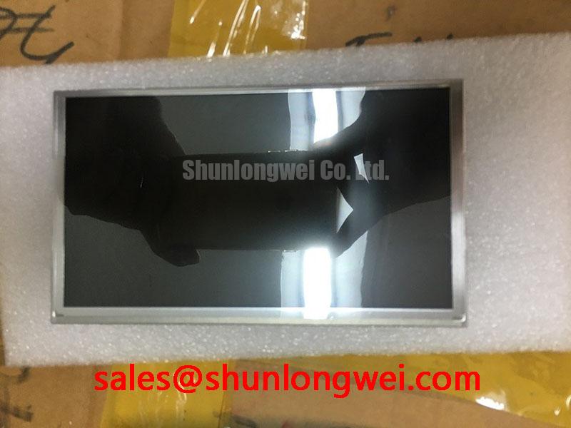
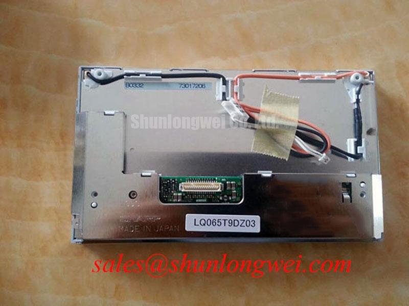
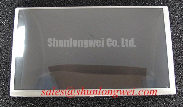
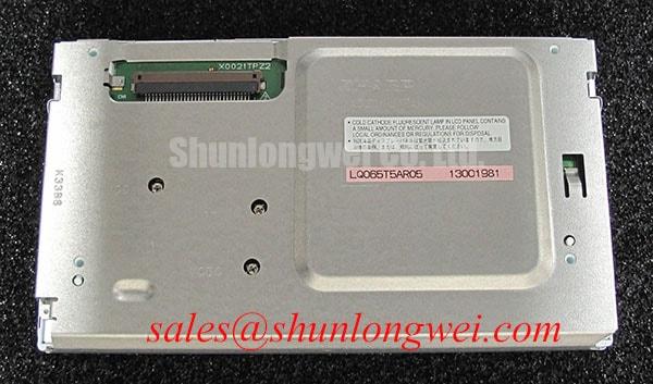
Before installing LQ065T5AR05, isolate the equipment supply, inspect the display connector and flex cable, and compare the replacement module’s label with the original service documentation. The available factory data identifies this unit as a Sharp TFT LCD Display Module for industrial LCD and HMI applications. Electrical interface details, optical ratings, dimensions, touch configuration, and backlight specifications should be confirmed against the original panel documentation before system power is applied.
| Manufacturer | Sharp |
| Model | LQ065T5AR05 |
| Product category | TFT LCD Display Module |
| Package or enclosure | TFT LCD Display Module |
| Specification status | Factory data reviewed; application details require confirmation |
The published factory information supplied for this product does not confirm a native resolution, active area, luminance value, viewing angle, interface pinout, logic supply, backlight type, response time, or touch technology. Those values must not be inferred from the model number. For a repair engineer, this distinction matters because a display with a similar diagonal size can still differ in connector assignment, timing requirements, backlight control, or mechanical fixing points.
In a dark industrial control cabinet, begin by separating the image generation problem from the illumination problem. Shine a controlled flashlight across the screen at an oblique angle while the panel is receiving a valid display signal. A faint image can suggest that the LCD logic is active while the backlight circuit requires further inspection, but this observation is not by itself a component level diagnosis. Check the display supply, enable signal, current or voltage feedback path, and the backlight connector against the original equipment schematic.
The supplied factory data does not identify whether LQ065T5AR05 uses CCFL or LED illumination. A CCFL replacement path therefore cannot be treated as a confirmed feature of this model, and an LED retrofit must not be assumed to be electrically compatible. CCFL systems can involve a high voltage ignition stage, while LED systems normally require a regulated current driver. These are different electrical architectures. The system integrator should verify the original backlight technology and the complete driver requirements from the panel documentation before selecting a retrofit assembly.
For a retrofit evaluation, the practical checks are connector compatibility, start up behavior, dimming control, thermal conditions, mechanical clearance, optical uniformity, and fault feedback. A replacement driver should be assessed for open load response and short circuit behavior because an incorrect feedback arrangement can produce repeated restart attempts, uneven brightness, or a shutdown indication that is mistaken for a failed LCD panel. The appropriate protection thresholds remain system determined and should be validated during bench testing.
Long term brightness claims also require careful separation between an official product specification and a general industry target. The available factory data for LQ065T5AR05 does not state a 50,000 hour half brightness value, MTBF figure, acoustic noise limit, or luminance decay curve. Such figures should not be presented as ratings for this specific Sharp module without a supporting datasheet or qualification report. Engineers evaluating a replacement should record initial brightness, driver temperature, dimming behavior, and visible uniformity, then compare the results with the equipment’s service requirement.
Low ambient temperature can increase liquid crystal response time and make motion artifacts more visible. This is a Design Consideration rather than a confirmed rating for this model. If the panel is considered for an exposed cab, earthmoving machine console, or telematics display, the enclosure designer should verify the specified operating temperature, condensation control, heater strategy, optical cover, and vibration conditions from the original equipment requirements. A heater strip must be controlled by the system designer and validated so that warm up behavior does not exceed the panel’s documented electrical or mechanical limits.
For a related display architecture review, engineers can also examine LMS700KF01-001 as a separate system component reference. It should not be treated as an automatic substitute or as proof of compatibility with LQ065T5AR05.
20 Pin and 30 Pin Differential LVDS Timing, Pixel Clock and Skew Compensation
Do not connect a replacement screen solely because the connector appears to have the same number of contacts. The available factory information does not confirm whether LQ065T5AR05 uses a 20 pin interface, a 30 pin interface, LVDS, parallel RGB, or another signal arrangement. Before energizing the module, identify the original panel cable, connector keying, pin one orientation, supply rails, enable lines, and timing signals from the equipment schematic or the original panel document.
Logic supply voltage is especially important. The system integrator should verify the required supply voltage from the original panel documentation rather than assuming a 3.3 V or 5.0 V input. The same caution applies to power on sequencing. The host controller should establish the required relationship between logic power, display enable, reset, backlight enable, and video data according to the confirmed interface specification. If the screen remains blank, monitor the supply and control lines with an oscilloscope while comparing them with a known good unit or service waveform.
When a differential interface is confirmed by documentation, the PCB designer should maintain a continuous reference plane, minimize unnecessary discontinuities, and route the pair as a controlled differential structure. The characteristic impedance, pair matching, connector transition, cable length, and system noise environment are design variables that require validation by the system engineer. The commonly used 100 ohm differential target is a Design Consideration for many LVDS systems, not an official LQ065T5AR05 specification in the supplied data.
Split screen images, repeated vertical bands, unstable colors, or intermittent synchronization can have several possible sources, including incorrect data mapping, cable contact resistance, timing mismatch, inadequate grounding, or signal integrity problems. Do not assign one cause from the visual symptom alone. Confirm the panel’s JEIDA or VESA mapping, lane order, pixel clock range, bit depth, and polarity settings from the controller documentation. If the interface is suspected, compare differential waveforms at the transmitter and receiver while checking the cable seating and chassis bonding.
A visually similar replacement such as LM64P10 should be evaluated only through a documented comparison of active area, resolution, connector definition, electrical timing, mounting geometry, and backlight requirements. Similar product category does not establish direct interchangeability. This comparison is useful during emergency repair planning, but the final decision remains dependent on the host system and verified documentation.
⚠️ Field Alert: Disconnect equipment power and allow the system to discharge before inserting or removing the display cable, because live contact can expose signal and supply pins to unintended electrical stress.
Super IPS and MVA Wide Symmetric Viewing Cone for Multi Angle Consoles
The available factory data does not identify the LQ065T5AR05 liquid crystal mode, viewing angle, contrast ratio, surface treatment, or touch construction. Values such as 85 degrees in four directions, Super IPS, MVA, anti glare etching, or anti reflection coating must therefore be verified rather than assigned to this model. This is important in a heavy mining shovel or earthmoving equipment telematics display, where the operator may view the screen from an offset position under changing daylight, dust, and cab lighting conditions.
For an optical compatibility review, inspect the screen with the intended cover glass, bezel, and sunlight direction. Check whether the displayed warning colors remain distinguishable when viewed from the normal operator positions. A panel that appears acceptable on a workbench can behave differently after installation because cover reflections, enclosure depth, polarizer orientation, and ambient illumination affect readability. These are system level Design Considerations, not confirmed characteristics of the Sharp module.
Anti glare and anti reflection treatments should also be treated separately. An anti glare surface can reduce mirror like reflections but may influence perceived sharpness and black level under direct light. An anti reflection treatment can reduce reflected light without providing the same surface texture. The correct choice depends on the equipment window, cleaning method, operator gloves, and required image contrast. The supplied information does not confirm whether LQ065T5AR05 includes either treatment.
If the unit is being evaluated for an industrial HMI, monitoring panel, or vehicle console, test the actual user interface rather than a static color screen only. Review alarm text, fine characters, trend lines, status icons, and dark background graphics from the normal viewing positions. When a touch layer is present in the original assembly, confirm its technology and controller separately. The supplied factory description identifies a TFT LCD Display Module but does not confirm resistive touch, capacitive touch, glove operation, or reliable operation with water on the surface.
For harsh equipment environments, enclosure sealing, cable retention, vibration control, and cleaning procedures should be verified as part of the complete assembly. Additional engineering context is available in Industrial Display and HMI Solutions, while compatibility with this particular Sharp model still depends on the original equipment specification.
Flashlight Dark Shadow Optical Diagnostic to Isolate Logic and Backlight Faults
Start a bench diagnosis by documenting the symptom before removing the panel. Confirm whether the host controller detects the display, whether the screen changes when the video source changes, and whether any faint image is visible under oblique flashlight inspection. This three stage approach helps classify the fault without turning a visual symptom into a fixed diagnosis.
- Apply a known valid video pattern and observe whether the image contains stable text, changing content, or no recognizable information.
- Inspect the panel with an angled flashlight to determine whether image content is present beneath the dark screen.
- Measure the documented display supply and control signals, then compare the readings with a known good signal path before testing the backlight driver.
A faint image can indicate that the logic path is operating while illumination is absent, but it may also accompany a timing fault, incorrect enable state, or damaged connection. A completely uniform dark field does not prove that the LCD cell, timing circuitry, or host controller has failed. Use the equipment schematic, connector documentation, and oscilloscope measurements to separate these possibilities.
Backlight troubleshooting should proceed from the source toward the load. Verify the driver input, enable command, protection status, output behavior, and connector continuity. An open circuit can cause a driver to enter protection or restart, while a short condition can produce a different protection response. The exact behavior depends on the driver topology and is not specified for LQ065T5AR05 in the supplied factory data. Do not bypass protection during diagnosis; locate the fault through controlled measurements and the manufacturer’s service procedure.
Line defects, dark columns, localized bands, or image changes after gentle cable repositioning may warrant inspection of the cable and connector before the panel is condemned. Internal display construction and bonding details for this model are not confirmed in the supplied data, so no specific internal fracture mechanism should be assumed. Compare the defect with a known good source, inspect for contamination or mechanical stress, and record whether the fault follows the panel, cable, or controller.
Backlight life and brightness decay must also remain separated from confirmed product data. No official luminance half life, MTBF, LED current, CCFL rating, or degradation curve has been supplied for LQ065T5AR05. A system qualification program may measure brightness over time under the actual driver, temperature, duty cycle, and enclosure conditions, but those results would be field or laboratory data for that test configuration rather than an automatic factory rating.
For procurement and repair records, identify the module as Sharp LQ065T5AR05, retain the verified product category as a TFT LCD Display Module, and require interface, optical, backlight, and mechanical confirmation before installation in a heavy equipment telematics console.