Content last revised on October 2, 2026
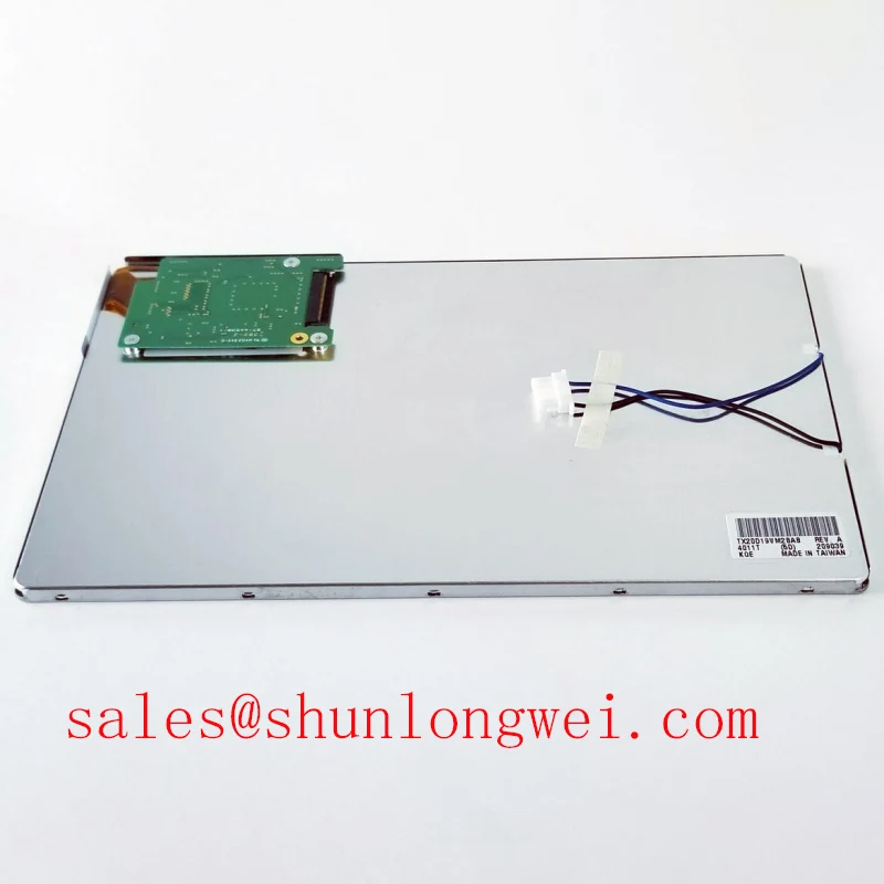
TX20D19VM2BAA KOE / Hitachi Industrial TFT LCD Display
Begin a replacement inspection by comparing the installed panel’s label, connector position, mounting outline, and visible optical surface with the documented TX20D19VM2BAA unit before applying power. This product is identified in the supplied factory information as a KOE / Hitachi Industrial Grade LCD/HMI Panel, packaged as a TFT LCD Display Module with an Official Factory Spec Verified status.
For overseas repair engineers and purchasing teams, the practical starting point is physical and interface compatibility. The available factory data confirms the product category and module identity, but it does not confirm a universal supply voltage, LVDS or TTL pin assignment, resolution, viewing angle, backlight type, touch configuration, or mechanical drawing. Those items should be checked against the original panel documentation, the equipment service manual, and the system’s known good display assembly before integration.
| Parameter | Verified information |
|---|---|
| Model | TX20D19VM2BAA |
| Manufacturer | KOE / Hitachi |
| Product category | Industrial Grade LCD/HMI Panel |
| Module construction | TFT LCD Display Module |
| Specification status | Official Factory Spec Verified |
The model may be evaluated for industrial HMI assemblies, diagnostic display terminals, control consoles, and other equipment where the original panel documentation confirms compatibility. For a same size or same resolution comparison, engineers can review TX20D200VM2BVA as a separate reference model. It should not be treated as an automatic substitute because connector wiring, timing, mounting features, optical performance, and backlight control can differ between closely related display modules.
Thermal Cycling Degradation of Polarizer Adhesives and Sealant Gasket Integrity
When the TX20D19VM2BAA is removed from equipment exposed to repeated temperature changes, inspect the polarizer surface, perimeter seal, frame, and connector area under controlled lighting. Look for lifting at the edge of the optical film, local discoloration, contamination near the perimeter, mechanical distortion, and signs that the module has been compressed unevenly by the enclosure. These observations are useful maintenance findings, but they do not establish a specific internal failure mechanism without manufacturer test data.
Liquid crystal response can change as temperature moves away from the panel’s specified operating window. At low temperature, a display may show slower gray transitions, motion smearing, or delayed image settling. At elevated temperature, optical uniformity and adhesive stability require evaluation against the original panel specification. The supplied factory information does not provide a confirmed operating temperature range for this model, so the system integrator should obtain that value from the original KOE or Hitachi documentation rather than applying a generic industrial LCD temperature rating.
For a high precision surgical navigation or ultrasound diagnostic display, image behavior should be assessed with the actual controller, image format, backlight setting, and enclosure airflow. A cold start test can record image appearance during warm up, while a controlled thermal inspection can compare gray transitions, uniformity, and edge integrity at the intended equipment limits. If a visible response delay occurs, verify the video source timing and panel drive conditions before assigning the symptom to liquid crystal viscosity alone.
Backlight control also requires system level confirmation. If the equipment uses PWM dimming, the driver documentation should be checked for its permitted frequency range and duty cycle behavior. A practical engineering recommendation is to evaluate a 200 Hz to 1 kHz PWM range only when it is supported by the selected backlight driver and panel interface. The test should check visual flicker, acoustic behavior, camera interaction, and brightness linearity across the complete dimming range. This range is a design consideration, not a confirmed TX20D19VM2BAA factory specification.
The display assembly should not be clamped against the active area or forced into an enclosure opening that is smaller than the original mechanical outline. Sealant, gasket compression, and bezel contact should be assessed from the equipment drawing. The module’s factory information supplied here does not include gasket material, adhesive construction, or sealing performance, so those properties should not be inferred from the model number.
Suppressing Pixel Jitter and Horizontal White Lines Induced by Adjacent 400 V Motor Drives
When a display is installed near a variable frequency motor drive, begin troubleshooting by separating image source problems from cable coupling. Capture the known good signal path, check the panel connector orientation, and inspect the LVDS or TTL cable for crushed sections, loose retention, or routing alongside high current switching conductors. A horizontal white band or unstable pixel edge can result from several conditions, including signal integrity loss, grounding differences, timing incompatibility, power disturbance, or panel damage.
The TX20D19VM2BAA factory information supplied here does not confirm a particular LVDS pinout, TTL assignment, pixel clock, data format, or cable shield termination. The integrator should therefore verify the original panel drawing before changing the controller or rewiring the harness. JEIDA and VESA data mapping are not interchangeable assumptions; the selected transmitter configuration must match the receiver mapping documented for the display assembly.
For equipment positioned near a 400 V motor drive, a design consideration is to keep the display data path physically separated from motor output wiring and switching nodes. Where a shielded FFC or LVDS cable is specified by the equipment design, its shield termination should follow the system grounding architecture rather than being connected at random points. A common mode ferrite may be evaluated where conducted interference is observed, but its suitability depends on cable impedance, data rate, signal amplitude, and the required common mode performance.
Use an oscilloscope or suitable differential probe to compare the suspect channel with a known good channel at the receiver side. Check for excessive ringing, duty cycle distortion, common mode movement, and timing displacement while the motor drive changes operating state. The measurement should be made with the final cable length, enclosure, grounding arrangement, and display controller in place. A bench test with a short temporary cable can hide the coupling mechanism present in the installed equipment.
💡 Pro Tip: Keep the differential display pair routed as a controlled, closely coupled path with consistent reference continuity, then validate clock and data timing at the panel connector rather than relying only on a continuity check.
Power sequencing is another compatibility point. The original equipment documentation should define the relationship between panel supply, logic enable, video transmission, and backlight enable signals. Do not assume that a replacement controller can apply power in any order. If the panel remains blank while the backlight operates, check the video enable state, data format, cable mapping, and supply behavior as separate conditions instead of treating the symptom as proof of a defective LCD cell.
For related display and driver evaluation, the LM190E08-TLG6 can be reviewed as a separate display solution reference. It should not be presented as a direct electrical or mechanical replacement for TX20D19VM2BAA without a complete interface comparison.
Surface Anti Glare and Anti Reflective Treatment for High Ambient Readability
In a bright control room or diagnostic display enclosure, inspect the TX20D19VM2BAA viewing surface for reflections from overhead lighting, surgical lamps, protective windows, and operator positions. Surface readability depends on the panel’s optical treatment, image luminance, ambient light geometry, cover glass, bezel depth, and viewing direction. The supplied factory parameters identify this product as a TFT LCD module but do not confirm an AG etched surface, AR coating, contrast ratio, viewing angle, or grayscale mode.
Anti glare and anti reflective functions should be distinguished during evaluation. An AG surface scatters incident light and can reduce mirror like reflections, but excessive scattering may soften fine image detail. An AR treatment can reduce reflected light through optical design, while its performance depends on wavelength, surface cleanliness, cover construction, and angle of incidence. These characteristics must be verified from the applicable KOE or Hitachi documentation or by comparing an approved sample in the final enclosure.
For medical equipment examples such as surgical navigation and ultrasound image terminals, engineers should examine the display from the actual operator eye positions rather than from a single normal viewing angle. If the image changes significantly as the operator moves laterally or vertically, verify the panel’s documented viewing characteristics and the image source configuration. Do not assume that a TN, IPS, or MVA classification applies to TX20D19VM2BAA unless the original specification sheet explicitly states it.
Video interface timing should be checked alongside optical testing. A TTL or LVDS transmitter must match the panel’s documented clock polarity, data order, color mapping, frame timing, and enable behavior. Clock jitter and data hold margin are system properties affected by the transmitter, cable, connector, power integrity, and temperature. When the display is used across an industrial temperature window, the complete signal path should be tested at the specified environmental limits rather than qualified only at room conditions.
Touch functionality requires the same discipline. The factory data supplied for this model does not confirm a resistive or capacitive touch layer, glove operation, water tolerance, controller type, or touch connector. If the equipment requires operation with surgical gloves or in the presence of surface moisture, the integrator should verify the original touch panel documentation and test the complete front assembly. A bare LCD module and a touch enabled display assembly are not interchangeable descriptions.
Mechanical readability can also be affected by the enclosure aperture. Confirm the visible area, bezel overlap, panel flatness, cover window, and mounting references from the original mechanical drawing. A replacement that fits electrically may still cause edge masking, uneven pressure, or a mismatch between the active image area and the front opening.
Additional engineering background on display integration, enclosure considerations, and harsh environment evaluation is available in Industrial Display and HMI Solutions. The linked material should support system evaluation, while the TX20D19VM2BAA factory specification remains the controlling source for model specific limits.
Solid State WLED Constant Current Driving and PWM Dimming Evaluation
Before connecting the backlight, identify whether the original equipment uses an integrated backlight assembly, a separate constant current driver, or another documented illumination topology. The supplied TX20D19VM2BAA information does not confirm WLED, CCFL, backlight voltage, backlight current, connector pinout, open load behavior, short circuit protection, overvoltage protection, PWM input level, or brightness control method. The system integrator should verify the required supply and control signals from the original panel documentation.
Replacing a legacy display can expose differences in backlight control even when the image connector appears similar. A CCFL system may require a dedicated inverter and high voltage ignition arrangement, while a WLED assembly generally requires a compatible constant current driver. Those architectures should not be mixed based on connector appearance. The driver must be selected from the documented electrical requirements of the actual panel assembly.
For PWM dimming, evaluate the complete operating range for flicker, audible noise, brightness linearity, camera interaction, and startup behavior. A 200 Hz to 1 kHz evaluation window can be used as an engineering starting point only when the driver and panel documentation permit it. A claimed 1000 to 1 dimming ratio or a specific lifetime value should not be assigned to this model without an applicable factory datasheet or qualified test report.
Backlight fault diagnosis should begin with the driver’s status output, enable state, current regulation behavior, and connector continuity. If the backlight switches off, inspect whether the driver reports an open load, short circuit, thermal event, or input undervoltage condition. The same symptom can arise from a control signal mismatch, a protection threshold, a damaged harness, or a panel backlight fault, so measurement at the driver and panel interface is more reliable than a single symptom based conclusion.
For cold equipment starts, assess brightness rise time and image visibility under the specified environmental conditions. A heater strip, enclosure warmer, or modified startup sequence should be considered only after the panel and driver manufacturer limits are confirmed. The model information supplied here does not establish a −20°C or −30°C operating rating, a gray to gray response value, a heater requirement, or a 50,000 hour half life. These figures must come from authoritative documentation before they are used in a product qualification plan.
During final integration, record the controller model, cable assembly, power sequence, backlight driver, enclosure opening, and environmental test conditions. This creates a reproducible replacement baseline for maintenance teams without assigning unsupported performance claims to the TX20D19VM2BAA.