

Content last revised on October 25, 2026
Logic Supply Voltage Sequencing and Interface Compatibility
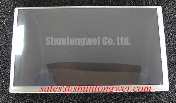
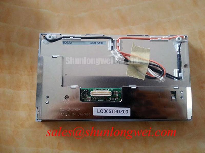
Start with the host system’s documented supply rails and panel interface, rather than applying a generic 3.3 V or 5.0 V assumption to the LQ065T9DZ03A. The confirmed product details here do not establish its logic voltage, power-on timing, connector pinout, or whether its interface is TTL or LVDS. Read the panel and controller documentation together, then compare connector orientation, pin assignments, signal names, and any enable or backlight-control lines before connecting power.
For an image split, intermittent, or absent at startup, inspect the signal path in a controlled sequence: verify that the host is configured for the panel’s specified mapping and timing, check that the cable is fully seated and undamaged, and compare clock and data activity with a known-good host configuration where available. JEIDA and VESA mappings are not interchangeable assumptions; select the mapping only from the relevant panel or system documentation. Likewise, differential routing impedance and transmitter timing are properties of the complete interface design, not specifications that can be assigned to this model from its product category.
As a design consideration, assess signal integrity across the equipment’s actual temperature range and operating conditions. Cable routing, connector retention, grounding, and transmitter timing can affect displayed image quality, but a symptom alone does not identify a single failed component. In a substation console, document the existing configuration before changing firmware or display settings, so a panel fault can be separated from a controller or cable issue.
Humidity, Storage Conditions, and Condensation Precautions
Moisture management begins before installation: inspect the enclosure, panel perimeter, and mating surfaces for trapped condensation, dust, or residue, and allow equipment to stabilize to its operating environment before energizing it. The available product information does not establish a humidity rating, storage limit, sealant construction, or thermal-cycle range for the LQ065T9DZ03A. Do not treat commonly cited environmental figures as this model’s qualified limits.
At low temperatures, liquid-crystal response can become slower, making motion appear less fluid or transitions appear delayed. That general behavior is useful when diagnosing a cold-start complaint, but the permitted operating range and response-time characteristics must come from the applicable panel documentation. Record whether the symptom changes as the assembly warms, and compare it with the host’s startup behavior rather than compensating blindly in software.
Mechanical sealing also affects service life at the system level. A gasket that is unevenly compressed can leave a path for contaminants, while an unevenly tightened bezel can transfer stress into the display assembly. As a design consideration, maintain even support and avoid twisting the panel during mounting; inspect the gasket for displacement or compression damage whenever the enclosure is opened. Maintenance note: Check enclosure airflow and gasket seating during scheduled service, and let cold equipment acclimatize before applying power if condensation is possible.
For a broader explanation of display technologies and selection factors, refer to The Ultimate Guide to Industrial TFT LCD Technology. It can help frame a system-level review, while model-specific limits still need to be established from the relevant documentation.
Backlight Thermal Management and Optical Assembly Care
Before diagnosing uneven brightness or a localized bright or dim region, distinguish panel-image behavior from backlight behavior. Check whether the symptom follows image content, appears across the full screen, or remains fixed in one area. Inspect the bezel, mounting surfaces, and ventilation path for pressure points, obstruction, or dust buildup. Such checks can identify installation or enclosure influences without attributing an undocumented optical material or backlight construction to the LQ065T9DZ03A.
The confirmed product description does not identify the backlight technology, luminance, dimming method, LED lifetime rating, or optical plate material. Therefore, LED rail temperatures, PMMA light-guide behavior, CCFL ignition voltage, and lifetime figures should not be treated as specifications for this model. When evaluating thermal conditions, measure the assembled equipment under its actual operating pattern and compare results with the panel’s approved limits. Keep heat sources and airflow restrictions in view, especially where the display is mounted close to power electronics.
In an HMI that holds static protection diagrams or status screens for long periods, vary screen content where the application permits and follow the display system’s own image-retention guidance. Persistent marks can have multiple causes, and observation alone does not prove permanent panel damage. Keep brightness and backlight controls within documented system limits, and record changes before adjusting them so that the original operating condition can be restored.
Where the display uses a separate backlight or driver assembly, verify its electrical and mechanical compatibility independently; do not infer a matched pairing from product category alone. The TX20D28VM2BPA is a separate display-related product that may be reviewed as part of a broader display-system topology assessment, not as a confirmed companion for this Sharp module.
Brightness Changes and Retrofit Evaluation
For a legacy console with declining brightness, compare the display under repeatable settings and inspect the backlight supply, controller configuration, and enclosure temperature before planning a retrofit. The LQ065T9DZ03A information provided here does not confirm CCFL or LED backlighting, a brightness-decay curve, dimming ratio, or rated lifetime. Avoid using generalized claims such as a specific half-life or MTBF as a model-specific service forecast.
A change from one backlight technology to another is a system redesign, not a direct panel substitution by default. The integrator should verify connector pinout, supply requirements, control signals, mechanical envelope, optical performance, and any applicable safety or emissions requirements for the complete equipment. Acoustic noise or unstable illumination should be investigated at the driver and assembly level; replacing a panel without checking these elements may leave the original symptom unresolved.
When comparing candidate replacement panels, confirm the resolution, active area, interface, connector, mounting geometry, and environmental limits against the installed unit’s records. LQ64D343 can be included in a replacement evaluation, but the link does not establish it as a verified direct substitute for the LQ065T9DZ03A. For a SCADA dispatch terminal or protection relay interface, validate the candidate in the actual host system before approving a maintenance change.