
Content last revised on October 27, 2026
SKIM300GD126DL Operational Boundaries: Evaluating Negative Gate Bias vs Active Miller Clamp Limits
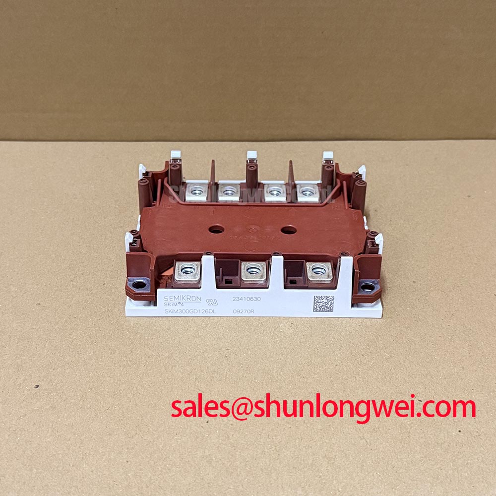
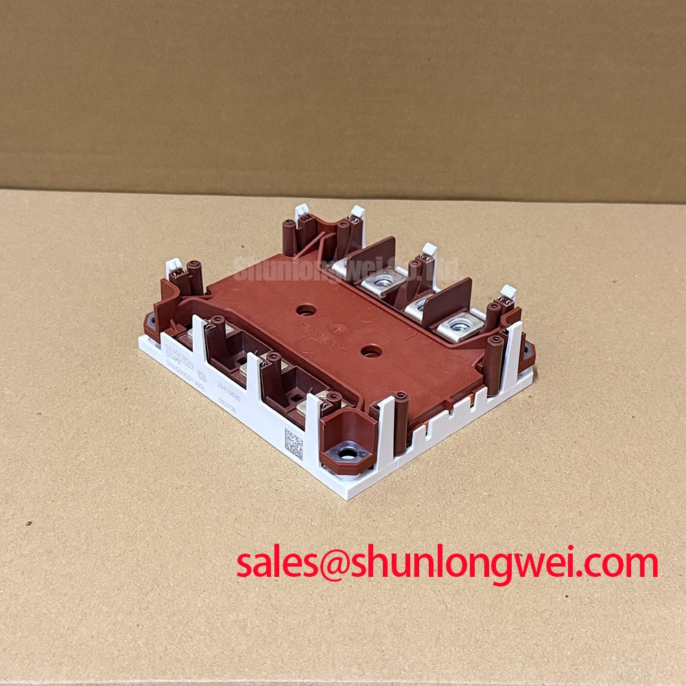
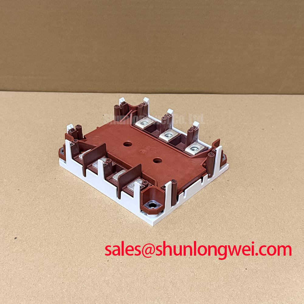
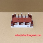
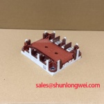
With the DC link isolated and verified discharged, match the SKIM300GD126DL terminal markings to the circuit drawing before connecting a diode-test meter. For this Semikron IGBT module, record probe polarity and compare equivalent power paths under the same cold conditions. Package designation, voltage, current, gate limits, terminal assignments, and insulation test conditions require the model-specific datasheet rather than interpretation of the part number.
During incoming inspection of the SKIM300GD126DL, separate the module from parallel circuit paths before interpreting readings. A diode-mode measurement can reveal directional conduction or a conspicuous mismatch, but it does not establish rated-current performance, switching behavior, or dielectric withstand. Bench Tip: Use ESD-controlled handling and compare cold readings with a documented reference under identical probe polarity and gate conditions.
Check the gate-to-emitter waveform of the commanded-off switch while its complementary switch commutates. As a Design Consideration, collector-voltage transitions can couple displacement current through the gate-collector capacitance and raise the inactive gate potential. A disturbance warrants investigation of the driver return, gate-loop impedance, and measurement arrangement before attributing it to a damaged module.
Negative gate bias and an active Miller clamp address this mechanism differently. Negative bias provides additional separation from turn-on, while a clamp supplies a low-impedance discharge path when its activation conditions are satisfied. Neither is an interchangeable substitute for checking the driver’s operating sequence. The selected bias must remain within the module’s documented gate limits, including transient excursions; clamp engagement depends on the particular driver circuit.
As an Engineering Recommendation, trace the clamp connection and gate return physically rather than judging only their schematic proximity. Shared return impedance can compromise the apparent off-state voltage. Observe at the module terminals with an appropriately rated differential measurement arrangement, and distinguish genuine gate movement from probe-loop pickup. Electrical clearance must follow the equipment’s insulation coordination requirements, not an assumed distance derived from package size.
For compatibility assessment in a heavy-duty variable-frequency AC motor drive, compare the complete terminal map, switching topology, mounting interface, and protection arrangement. The separately listed SKKR300/0.2-BVR should not be treated as an interchangeable replacement based on a similar current-related designation; its device function and circuit connections require independent evaluation.
Transient Dynamics & Electrical Design: Driver Power Stage Start-Up Inrush Mitigation on SKIM300GD126DL
Verify that the driver establishes its intended off-state gate condition before the power circuit can energize. As a Design Consideration, auxiliary-rail inrush or supply collapse can leave a driver between its normal operating state and undervoltage lockout. Monitor the driver rails, enable signal, fault output, and gate voltage together during startup and shutdown.
Where the driver uses a negative supply, examine whether that rail becomes valid before switching permission is released. Check the reverse sequence during power removal as well: residual DC-link energy can remain after auxiliary power disappears. Interlock timing and acceptable rail thresholds belong to the selected driver and equipment design; they are not intrinsic timing specifications of the SKIM300GD126DL.
Keep complementary power-stage comparisons topology-specific. A separate device such as SKM100GB176D requires its own driver-load, voltage-class, and terminal review rather than inheriting this module’s control assumptions. Likewise, upstream phase-controlled rectification and line-harmonic mitigation are converter-level functions, not properties established by the IGBT module designation.
Insulation checking also needs a controlled procedure. Consult the manufacturer’s specified test connections and conditions before applying a withstand test, with sensitive driver electronics disconnected as required by the equipment procedure. A handheld resistance check is not equivalent to a dielectric withstand test, and neither measurement alone establishes an operating insulation margin.
SKIM300GD126DL Thermal-Electrical Optimization: Mitigating Commutation Turn-Off Voltage Spikes Through Practical Tuning
Capture collector-emitter voltage and commutating current together when investigating turn-off overshoot. As a Design Consideration, loop inductance produces additional voltage during current change, while freewheeling-diode recovery can influence the complementary switch’s turn-on stress. Compare waveforms at matched load and temperature before changing gate resistance or adding a snubber.
Reduce unnecessary commutation-loop area while preserving required clearances. Gate-resistance changes affect switching loss as well as transient behavior; an RC snubber introduces dissipation and pulse-loading requirements of its own. Select either approach from measured waveforms and component limits, then check both switching directions rather than accepting improvement at a single operating point.
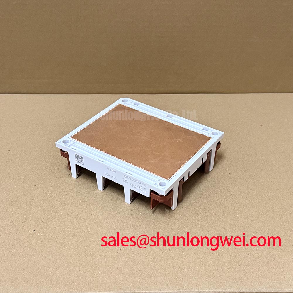
Thermal assessment should combine conduction and switching losses with the documented transient thermal impedance and actual cooling boundary conditions. The background article The Advanced Thermal Management Revolution provides broader context, while Semikron-Danfoss SKiiP® Technology describes a manufacturer technology platform, not proof of this model’s internal construction. During tuning, record case temperature, cooling conditions, and switching frequency together so that reduced overshoot is not accepted at the expense of excessive thermal loading.