
Content last revised on September 13, 2026
SKM100GB176D Identification and Operating Boundaries
Before applying power, verify the installed module marking against the required SKM100GB176D part number and confirm that the equipment’s voltage and current boundaries remain consistent with its 1700 V and 100 A official ratings.
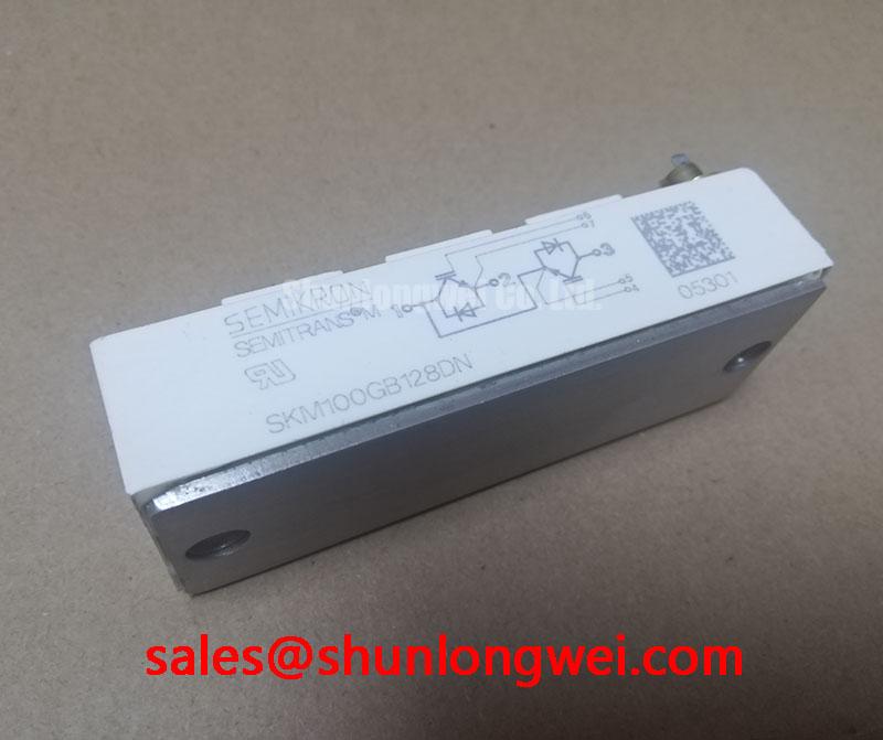
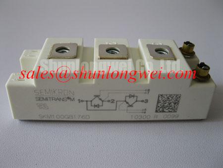
The SKM100GB176D is a Semikron IGBT module supplied in the Semitrans package. Its stated voltage and current values are Official Specifications and should be treated as component identification limits, not as complete permission to operate a converter at any particular DC link voltage, switching frequency, cooling condition, or overload duty. System operating limits depend on the original converter design, gate driver behavior, protection response, thermal path, and measured switching waveforms.
| Parameter | Specified Value | Classification |
|---|---|---|
| Model | SKM100GB176D | Official identification |
| Manufacturer | Semikron | Official identification |
| Voltage rating | 1700 V | Official Specification |
| Current rating | 100 A | Official Specification |
| Package | Semitrans | Official Specification |
For equipment repair, preserve the original gate drive board, busbar arrangement, cooling architecture, protective sensing path, and terminal insulation arrangement unless the complete system has been revalidated. The module rating alone does not establish the suitability of a changed mechanical assembly or a revised control board.
SKM100GB176D Operational Boundaries: Evaluating Thermal Interface Material Thickness Limits
Remove the previous thermal interface residue from both the heatsink and module base contact surfaces, then inspect the contact plane under suitable lighting before mounting the SKM100GB176D. Embedded debris, hardened compound, dents, or uneven residue can create localized thermal resistance even when the mounting hardware appears secure. A useful service check is to compare the removed module’s contact imprint with the replacement installation after a controlled seating operation, while avoiding assumptions about internal module construction.
Thermal interface material thickness is a Design Consideration rather than an official parameter for this model. In common power-module service practice, a thin, uniform interface layer in the approximate 50–100 µm range is often evaluated to fill surface irregularities without creating an unnecessarily thick thermal barrier. The applicable material, thickness, and application method must be verified against the converter manufacturer’s service documentation, heatsink flatness, and the selected interface product’s instructions.
Baseplate contact can be affected by heatsink curvature and local mounting distortion. Apply the specified fastening sequence from the host equipment documentation so clamping load develops progressively across the module footprint. If the original assembly uses spring hardware or Belleville washers, retain its intended stack order and orientation; those parts influence clamping consistency as thermal cycling occurs. Do not infer a replacement torque from generic fastener practice when the original equipment’s mounting specification is available.
⚡ Safety Interlock Note: Isolate the DC link, verify that stored energy is discharged by the approved site procedure, and confirm absence of hazardous voltage before touching module terminals or removing gate connections.
After reassembly, investigate abnormal heatsink temperature rise through evidence rather than a single assumed cause. Uneven compound coverage, a warped cooling surface, restricted coolant flow, altered switching behavior, and a changed load profile can each contribute. Thermal imaging, controlled load testing, and comparison with a known healthy phase or converter section can help separate a mounting issue from an electrical-loss issue.
SKM100GB176D Operational Boundaries: Evaluating Thermal Capacitance vs Heat Sink Limits
A heatsink temperature measured after a steady operating interval does not fully describe junction stress during a short overload, repetitive current pulse, or battery PCS power reversal. The junction-to-case thermal response is time dependent, so the peak junction estimate should be evaluated from the module’s applicable transient thermal data, the duration and repetition of the load event, the measured case condition, and the actual loss behavior of the installed converter. This is an Engineering Calculation when it uses documented thermal impedance curves and measured operating conditions.
For a utility-scale centralized battery energy storage PCS, bidirectional operation can produce different current waveforms during charge and discharge. Designers should verify whether the original thermal model covers both power directions, recurring high-demand events, and the converter’s permitted transient profile. A heat sink sized only around average dissipation can conceal short cyclic junction excursions that are significant to the protection and cooling assessment.
Busbar geometry is equally relevant during switching checks. A Design Consideration is to minimize the commutation-loop inductance between the DC-link capacitor, the switching module, and the return path, because stray inductance can add transient voltage during current transitions. The appropriate geometry, capacitor placement, snubber arrangement, and permissible peak margin are system-determined and should be verified with appropriately rated differential voltage and current measurement equipment during switching tests.
Film capacitors used for local decoupling should be assessed in the context of their actual connection path, termination quality, ripple duty, and insulation spacing. A capacitor located physically nearby may still be electrically ineffective if the conductor path is long or poorly coupled. When overshoot or ringing is observed, compare the waveform at the relevant module terminals against the original known-good layout before revising the gate resistance or adding suppression parts.
Semitrans-family packaging is part of the established industrial power-module landscape described by Semikron-Danfoss SEMITRANS® Industry Standard IGBTs. Package recognition does not substitute for matching the full electrical and mechanical requirements of the installed equipment.
Benchtop Waveform Tuning and Voltage Derating for SKM100GB176D
The 1700 V rating of the SKM100GB176D is an Official Specification. It should be checked against the actual DC-link operating envelope and measured switching transient, rather than treated as a target operating point. Gate-drive timing, load current, cable arrangement, local decoupling, temperature, and protection action all influence the voltage seen by a module during turn-off and fault events.
High-altitude operation and terrestrial neutron exposure are high-risk reliability topics that require manufacturer-specific qualification information or a validated system reliability study before numerical claims can be made. No failure-in-time rate, single-event burnout rate, altitude threshold, or operating-life prediction is asserted here for this model. As a Design Consideration, equipment intended for unusual altitude or environmental conditions should be reviewed against the system owner’s qualification requirements and the applicable manufacturer documentation.
At the bench, begin by verifying that the isolated gate drive is powered and referenced as intended by the original design. Check for unintended gate disturbance during the opposite switching transition, excessive collector-emitter overshoot, ringing, or irregular turn-off behavior. These observations may indicate a gate-loop, measurement, layout, load, or protection interaction; they do not prove one cause on their own. Oscilloscope probing technique and probe loop area must be controlled, since poor measurement setup can create misleading apparent ringing.
Dead time and desaturation protection belong to the converter’s control and protection design, not to an unverified replacement-module setting. When the original gate driver supports controlled fault shutdown, retain and validate its intended behavior using the equipment documentation and safe test conditions. The objective is to prevent shoot-through and constrain fault stress while confirming that the sensed collector-emitter response, driver isolation behavior, and shutdown sequence remain coherent under real switching conditions.
For broader test planning around drive layout, protection coordination, thermal interfaces, and switching topologies, use this IGBT Design & Integration reference as a practical starting point. Any final operating boundary must still be established from the specific PCS schematic, protection settings, and measured waveform margins.
Assembly Integrity & Layout Architecture: Managing High-C-Rate Battery Cycling for SKM100GB176D
In a bidirectional battery energy storage PCS, active power can reverse between battery racks and the converter link. That operating change can alter current direction, switching states, and the thermal cycling profile seen by power modules. Engineers evaluating the SKM100GB176D should therefore inspect both charge and discharge operating states, rather than validating only the more familiar inverter direction. The 100 A current rating remains an Official Specification; permissible system duty must be established from the complete converter design.
Mechanical integrity supports electrical repeatability. Confirm that power terminals are clean, correctly oriented, and secured according to the equipment manufacturer’s required assembly method. Maintain the intended creepage and clearance arrangement around high-voltage terminals, including any original barriers, covers, insulators, and cable routing features. A displaced barrier, altered conductor position, or compromised fastening arrangement can change insulation conditions and the effective commutation loop.
💡 Pro Tip: Keep positive and negative DC bus conductors closely coupled and geometrically symmetric where the original layout permits, then validate switching peak margins with a controlled double-pulse or equivalent system test.
For protection-board troubleshooting, inspect the isolation barrier, driver supply stability, command path, and fault feedback circuit before attributing a failed start or unstable waveform to the IGBT module. High common-mode switching conditions can expose weaknesses in an optocoupler or digital isolator implementation, but the relevant immunity requirement and validation method are system-specific. Compare behavior with the original schematic, service records, and a verified healthy assembly whenever available.
When a lower-voltage member of the same product family is being reviewed for a different equipment requirement, SKM100GB063D provides a neutral point of reference for a specification comparison. It is not an automatic substitute for SKM100GB176D; voltage class, gate-drive compatibility, package fit, protection settings, and converter qualification all require independent verification.
In related power-stage reviews, the SKM75GB07E3 can be considered as a separate component reference when documenting associated converter hardware. Its presence in a parts review does not establish interchangeability, identical electrical behavior, or suitability for the same position. Semikron-Danfoss product information is available through the Semikron-Danfoss Power Electronics & Modules Official Hub for further manufacturer context.