Content last revised on October 10, 2026
SKKE162-16E Circuit Protection and Reliability: Calibrating Regenerative DC Bus Voltage Surge Dissipation
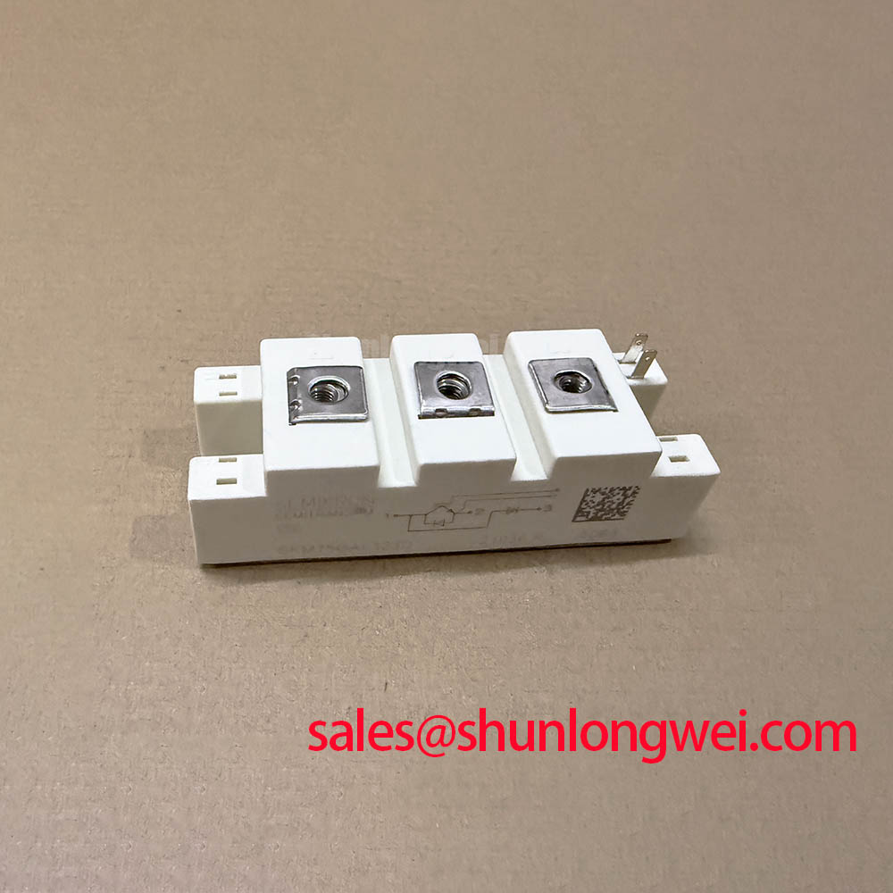
With the inverter isolated, I first compare the installed device marking with the replacement record, then inspect the DC bus path for a failed braking branch, loose power connection, or damaged resistor. The SKKE162-16E is identified here as a Semikron Semitrans thyristor module with a listed voltage rating of 1600 V and a listed current rating of 195 A. These ratings establish the component identity; they do not independently define the allowable surge, switching frequency, cooling condition, or braking energy of a complete drive.
In a regenerative drive, motor deceleration transfers kinetic energy into the DC link. A braking IGBT and ballast resistor must be coordinated with the DC-link capacitance, deceleration profile, repetition rate, resistor thermal capacity, and the controller’s overvoltage threshold. The SKKE162-16E is not itself identified here as the braking IGBT; it may instead be associated with another stage of the power circuit, subject to the original schematic. During commissioning, monitor the DC-link voltage while applying the intended braking sequence and compare the measured peak with the voltage boundary selected by the system designer.
A failed braking branch can leave the drive functional at light load while allowing the bus to rise during deceleration. Check the gate-control supply, isolation path, braking command, resistor continuity, and switching waveform as separate points in the chain. A shorted power path may also cause immediate overcurrent protection, so the module should remain disconnected from the active bus during cold resistance checks. Do not use a resistance reading alone to certify a high-voltage power semiconductor.
Layout is equally important. Keep the high-current commutation loop compact, separate control wiring from the braking power path, and provide physical clearance suitable for the actual working voltage and pollution environment. When reviewing the surrounding topology, the SKKR400/0.2-BVR may be evaluated as an associated rectification-stage component, subject to the original circuit diagram and electrical ratings.
Benchtop Waveform Tuning: Mitigating Long Motor Lead Reflected-Wave Voltage
Long motor cables can behave as transmission lines rather than simple low-impedance conductors. An impedance mismatch at the motor terminals can reflect fast switching edges toward the inverter, producing terminal peaks that may approach twice the local DC-link voltage in unfavorable installations. This behavior must be evaluated with a properly rated differential probe and a measurement connection that does not add excessive loop inductance.
For an industrial inverter welder or medium-frequency induction heating power supply, begin with the actual cable length, motor or load impedance, carrier strategy, and output filter arrangement. The SKKE162-16E voltage rating is a device parameter, while the permissible transient margin depends on the complete switching circuit. Designers should select any dv/dt filter, output choke, or motor-side network after measuring the switching edge and confirming the peak voltage at the relevant power terminals.
Phase-angle conduction and line-frequency ripple also influence the stress seen by the DC link. A poorly damped input or intermediate circuit can combine low-frequency bus ripple with high-frequency switching overshoot. Observe the waveform across the power terminals during startup, steady operation, load transition, and controlled shutdown. An RC snubber can reduce a ringing component when its placement, pulse energy, and capacitor voltage rating match the measured transient; it should not be added as a blind substitute for correcting excessive stray inductance.
When the waveform changes after a cable replacement, compare the original and new cable construction, shield termination, grounding arrangement, and output filter position. A control or gate-circuit adjustment may affect switching loss and electromagnetic emissions, but the final value is a system tuning result. The Semikron reference material on Semikron power modules provides useful background for evaluating power-module integration without treating a general product-family page as a model-specific switching guarantee.
Assembly Integrity and Layout Architecture: Managing Bolted Contact Oxidation and Gas Heating
At the power terminals, use a calibrated micro-ohmmeter to compare the bolted contact resistance with the equipment’s acceptance limit; the supplied maintenance focus identifies 10 µΩ as the audit threshold for this installation, not as an official SKKE162-16E datasheet rating. Measure the joint consistently, exclude probe contact resistance, and compare phase or branch readings under the same mechanical conditions.
Thermal imaging under controlled load can reveal an abnormal temperature profile around a terminal, busbar transition, or cable lug. A localized hot spot may reflect contact pressure, surface condition, conductor alignment, current crowding, or insufficient heat spreading. Record the ambient condition and load state with each image so that later comparisons are meaningful. If the temperature rises mainly at the joint rather than across the module body, inspect the mechanical interface before attributing the symptom to semiconductor loss.
The Semitrans package should be mounted on a clean, flat thermal interface with the specified hardware and installation method from the applicable mechanical documentation. Use a cross-pattern tightening sequence where the assembly instructions require it, prevent busbars from imposing bending force on the terminals, and keep control connectors away from high-current magnetic fields. Bench Tip: Use ESD protection and establish a cold-state semiconductor-junction and terminal baseline before applying any powered test.
For service replacement, compare terminal geometry, electrical polarity, mounting pattern, gate interface, and cooling arrangement rather than relying on current rating alone. The SK50DA100D can be reviewed as a separate candidate in a replacement assessment, but interchangeability must be confirmed against the original schematic, mechanical drawing, drive circuit, and protection settings.
SKKE162-16E Thermal-Electrical Optimization: Managing Commutation Turn-Off Voltage Spikes
During thyristor commutation, reverse-recovery behavior and a rapid current transition can contribute to voltage overshoot. Stray inductance in the commutation loop then converts that transition into additional voltage stress. Inspect the relevant voltage and current waveforms together, paying attention to the timing between the outgoing current, commutation event, gate signal, and DC-link disturbance.
An RC snubber is a possible damping network when the ringing frequency and energy have been measured. Its capacitor must withstand the repetitive voltage stress, while its resistor must tolerate the associated pulse energy and average dissipation. These are engineering calculations based on the observed waveform and repetition rate, not fixed values assigned to the SKKE162-16E. Minimize the commutation loop area and verify the resulting peak voltage at the module terminals during the intended operating sequence.
The gate circuit can also be checked for suitable pulse amplitude, duration, isolation, and wiring impedance. The appropriate arrangement is determined by the gate-control architecture, load current, operating frequency, commutation conditions, and thermal measurement. Check the gate signal at the module terminals rather than assuming that the controller-side signal represents the actual gate waveform.
High common-mode transients can couple through an isolated control circuit, causing false gate movement or timing distortion. Route the power loop and control return deliberately, maintain the intended isolation barrier, and verify the control circuit’s common-mode transient capability from its own documentation. For thermal packaging context, the Semikron sintering technology reference is relevant to general power-module construction, but it should not be used to infer unlisted internal materials or model-specific lifetime data.
When the module is evaluated for inverter welding equipment or medium-frequency induction heating, correlate electrical waveforms with heatsink temperature, terminal temperature, and protection-event logs. A stable cold-state measurement followed by controlled powered testing gives the repair engineer a clearer separation between assembly faults, control timing problems, load-side reflections, and genuine semiconductor stress.