Content last revised on October 4, 2026
Transient Dynamics and Electrical Design for SKKD260-12
Isolate the rectifier, discharge its energy storage, and compare the cold terminal readings of the removed SKKD260-12 with the equipment schematic before fitting a replacement. A low reading across a power path can reflect a parallel circuit rather than a failed module, so disconnect the relevant conductors before drawing a conclusion.
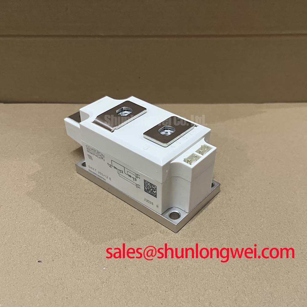
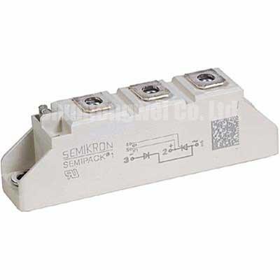
The SKKD260-12 is identified here as a Semikron SEMIPACK diode module. That distinction matters during a stopped-equipment repair: a diode conducts according to circuit polarity and does not accept a gate firing command. Trace the rectifier drawing from each AC connection through the module terminals to the DC bus, then match the physical terminal arrangement against the original equipment documentation. Do not infer polarity or connection order from the similarity of a neighboring module’s case.
The supplied listing records 200.0 V and 2601.0 A, but those entries should not be treated as confirmed Official Datasheet Specifications for this part. Before using either value to approve a repair, obtain the manufacturer’s part-specific datasheet and check the full ordering designation, voltage rating, current rating, test conditions, and outline drawing. Semikron Danfoss describes the broader SEMIPACK thyristor and diode module product line; a product-line description does not replace the rating table for the exact module.
Design Consideration: where switching elsewhere in the rectifier produces voltage spikes, inspect the existing suppression network and measure the waveform at the installed module under a controlled test. An RC snubber can influence transient voltage, while wiring inductance and fault-current rise affect device stress. Select component values only after the system designer has checked the circuit topology, measured transients, and consulted the applicable device limits. A series saturable reactor, if present in the original design, also needs to be evaluated against that design rather than added as an assumed requirement of this diode module.
On the bench, check for loose busbar joints, heat discoloration, damaged terminal threads, and uneven contact at the heatsink interface. Record which connections were removed; photographs taken before disassembly are useful when several mechanically similar rectifier positions sit side by side. Field Alert: Do not apply a generic mounting torque to the module; confirm the fastener and torque requirements in the applicable module and equipment documentation before tightening.
SKKD260-12 Circuit Protection in a Controlled Rectifier
A phase-controlled rectifier may contain both diodes and gate-triggered thyristors, but the firing angle belongs to the controlled devices and their trigger circuit, not to the SKKD260-12 diode itself. If DC output changes unexpectedly as the controller advances or retards firing, first identify the module’s position in the bridge. A diode-path fault, a missing thyristor gate pulse, an AC supply imbalance, and a DC-side load problem can produce overlapping symptoms. Compare phase voltages, gate-drive records where applicable, and current waveforms before assigning the fault to one module.
Design Consideration: changing the thyristor firing angle changes the rectifier’s output behavior and its demand on the AC supply. The relationship depends on the actual bridge configuration, commutation overlap, supply impedance, and load. An angle sweep from 0° to 150° describes a possible controller test range, not an operating range or transfer characteristic specified for this diode module. If such a test is permitted by the equipment procedure, log AC input and DC output together so that a falling DC voltage is not mistaken for proof of a diode fault. Power factor and reactive power must be assessed at the equipment level.
For a replacement assessment, compare the original bill of materials and schematic before considering another module family. The linked SKKT273/12E is a thyristor module; it is not an automatic substitute for an SKKD diode module merely because both appear in rectifier equipment. Likewise, an SKKD162/12 elsewhere in a power path may help identify the surrounding topology, but its ratings, connections, and mounting details require separate verification. These comparisons support fault isolation, not a cross-reference approval.
For protection checks, read the installed fuse marking and the equipment protection schedule, then obtain the fuse maker’s total-clearing data at the relevant voltage and prospective fault current. Pair that information with the exact SKKD260-12 datasheet’s surge-current and I²t conditions. Without both sets of curves and their test conditions, a fuse coordination claim would be premature. A continuity check can screen for an obvious short, but it cannot establish that a module has retained its surge capability after an abnormal event.
Thermal and Surge-Current Checks for SKKD260-12
Before energizing a repaired rectifier, inspect the mating heatsink surface and confirm that the module seats evenly. Remove old interface material according to the equipment service procedure and apply the specified replacement interface material consistently. Check that cables and busbars do not pull the case out of alignment as their fasteners are tightened. These mechanical details affect heat removal and connection resistance, yet they cannot be converted into a junction-temperature margin without the part-specific thermal data and operating measurements.
Surge-current ratings are especially easy to misuse. A datasheet value identified as ITSM for a 10 ms sinusoidal half-cycle describes a stated test event under stated initial-temperature and voltage conditions; it is not permission to repeat that surge during normal service. Verify the exact datasheet value, its conditions, and the permitted treatment of reverse voltage after the surge. Then compare the expected fault waveform and clearing time with those conditions. If the equipment has experienced repeated trips, investigate each event rather than assuming the original single-event rating remains available.
During a controlled restart, compare the repaired phase with other phases where the topology permits. Look for unequal current, unexpected forward drop, abnormal terminal heating, and changes in heatsink temperature. A temperature difference may point toward a connection, cooling, loading, or device issue; it does not identify one cause by itself. Design Consideration: capture readings after the equipment reaches a representative operating state, and let the system engineer decide whether the measured temperatures leave adequate margin under the manufacturer’s verified limits.
Diode technology discussions can clarify why reverse recovery and conduction losses matter in a rectifier, but they do not establish which die is fitted inside this specific module. Semikron Danfoss’s bare-die technology information is useful background when reviewing those mechanisms; use the SKKD260-12 datasheet for claims about this part. For a prospective green hydrogen electrolyzer DC power rectifier repair, check the actual bridge position, cooling arrangement, and duty profile before treating the application as compatible.
Assembly Integrity and Fuse Coordination for SKKD260-12
Lay out the removed module, fasteners, busbar hardware, and insulation components in connection order. Compare each item with the service drawing before reassembly, paying particular attention to terminal polarity, contact surfaces, and clearances. Confirm the SEMIPACK outline and mounting pattern against the equipment rather than relying on the family name alone. Where a terminal or mounting specification is missing from the available paperwork, stop short of assigning a torque or adding a washer arrangement by assumption.
Fuse coordination requires a comparison under the same prospective fault conditions. The fuse’s total-clearing I²t must be assessed alongside the diode module’s applicable non-repetitive withstand data, while peak let-through current, circuit voltage, initial temperature, and current path also remain relevant. Neither an I²t comparison by itself nor a semiconductor fuse label can guarantee that a dead short will cause no mechanical damage. The table below is a document check, not a substitute for the missing numerical coordination data.
| Document to check | Required comparison |
|---|---|
| Exact SKKD260-12 datasheet | Surge-current and I²t limits, including waveform and initial-temperature conditions |
| Installed fuse datasheet | Total-clearing I²t and peak let-through at the applicable voltage and prospective current |
| Equipment protection study | Fault location, available current, upstream protection, and permitted clearing sequence |
If a fuse has opened, preserve its marking and inspect the surrounding connections before replacing parts. Check the DC bus and associated loads for a persistent short, then test the rectifier paths according to the equipment’s isolation procedure. Re-energization should follow the site’s controlled commissioning process, with current and voltage waveforms observed for signs of an unresolved fault. For broader context on how alternative power-semiconductor technologies present different switching and integration questions, see Wide Bandgap Revolution; it does not change the ratings or protection requirements that must be verified for this Semikron module.