

Content last revised on September 22, 2026
SKM111AR Specifications and Replacement Verification
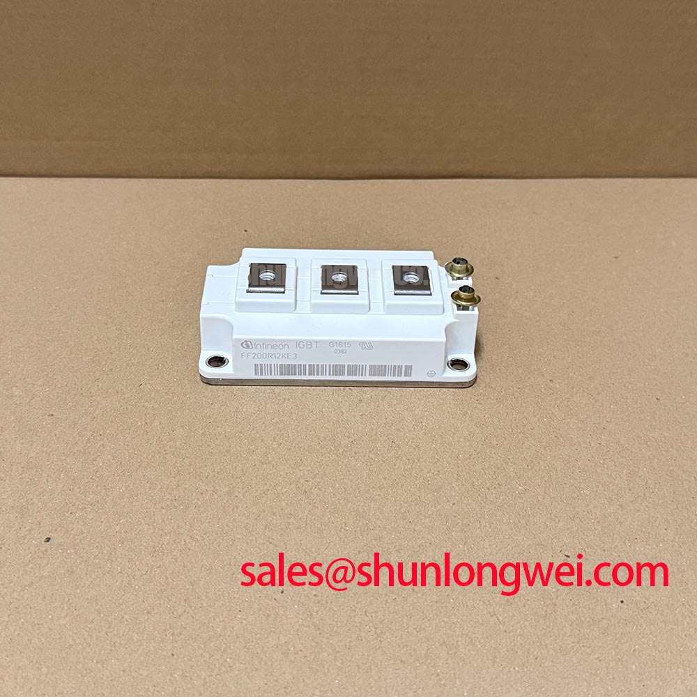
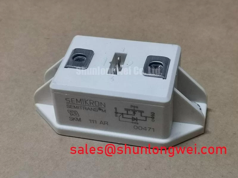
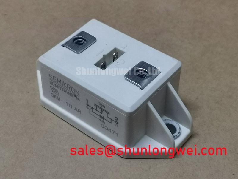
Verify the equipment nameplate and the removed module marking before reconnecting any power wiring: SKM111AR is specified at 1200 V and 200 A in a Semitrans housing. These are Official Datasheet Specifications and should be checked against the inverter’s original bill of materials, DC bus rating, cooling arrangement, and control-board documentation before replacement planning.
| Parameter | Official Specification |
|---|---|
| Product model | SKM111AR |
| Manufacturer | Semikron |
| Voltage rating | 1200 V |
| Rated current | 200 A |
| Housing | Semitrans |
| Product category | IGBT Module |
SKM111AR Thermal Electrical Optimization: Planar Symmetrical Busbar Geometry for Practical Tuning
During inverter repair, inspect the DC link busbar, module terminals, capacitor connections, and driver wiring as one current path rather than as isolated parts. The SKM111AR has a 1200 V voltage rating, but the peak stress present in a live converter is determined by the complete switching loop. Engineering Calculation considers peak voltage as the DC bus voltage plus the voltage generated by loop inductance during current change. This relationship should be assessed with system measurements during switching tests rather than assumed from the module rating alone.
As a Design Consideration, keep outgoing and return conductors physically close and geometrically balanced where the equipment layout permits. A planar, symmetrical busbar arrangement can reduce loop area and help suppress turn off overshoot. The capacitor path should be inspected for loose joints, oxidized contact surfaces, or long conductor runs that can increase inductive stress. When a snubber network is present, its capacitance, discharge path, insulation condition, and mounting should be verified against the original converter design.
For commercial string inverter and micro grid energy storage maintenance, compare switching waveforms with a known good phase or the original commissioning record where available. Ringing, unequal phase behavior, or unexplained protection events may indicate a layout, capacitor connection, gate drive, or measurement issue. They should not be attributed to the module alone without confirming the complete power stage.
For family level package context, consult the Semikron Danfoss SEMITRANS® power module portfolio alongside the original equipment documentation.
Preventing Spurious Faults During Parallel Current Sharing with SKM111AR
Parallel module arrangements require confirmation of the original circuit topology before any replacement is fitted. Static current distribution can be influenced by device conduction characteristics and temperature, while dynamic sharing depends heavily on matched power paths and gate drive loop behavior. The supplied specifications for SKM111AR confirm voltage, current, and housing information, but do not establish gate charge, switching speed, short circuit withstand capability, or temperature coefficient data. Those characteristics must be verified from approved original technical documentation.
As a Design Consideration, inspect whether parallel positions have comparable busbar path lengths, equivalent gate wiring routes, and similar thermal contact conditions. Unequal driver connections can produce different switching transitions even when modules carry similar steady state current. Oscilloscope verification at the original test points is preferable to adjusting gate components based only on an observed fault code.
Desaturation monitoring and controlled soft turn off are driver level protective functions. Their threshold, timing, and response profile must remain aligned with the converter manufacturer’s original design. Changes to protection timing can alter fault energy and switching stress, so system engineers should validate protection behavior under controlled conditions.
Where a maintenance team is reviewing related Semikron stock references, SKM100GB063D can be examined as a separate catalogue reference. Electrical topology, mechanical fit, driver compatibility, thermal capability, and equipment approval requirements must be confirmed before treating any different part number as a replacement.
For a technical discussion of turn off gate drive behavior, see Evolution of Negative Off Bias Gate Drive Circuits. The system integrator should verify that any gate drive method used is supported by the original module and converter documentation.
Preventing Spurious Faults Through Baseplate Thermal Grease Layer Control for SKM111AR
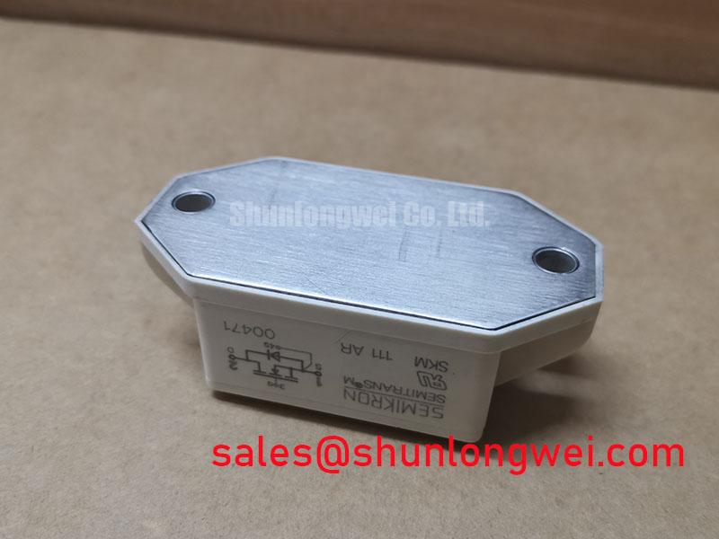
Before mounting an SKM111AR, clean the heatsink contact surface and inspect it for raised burrs, embedded debris, corrosion, or unevenness. Thermal interface material is intended to fill small surface imperfections, not compensate for damaged contact faces or warped mechanical assemblies. The required compound type, application method, layer thickness, and tightening sequence should follow the equipment manufacturer’s maintenance procedure because no mounting torque or thermal interface specification is provided in the supplied official data.
Apply thermal material consistently across the contact area and avoid trapped air pockets. Tighten mounting hardware in the prescribed sequence so the baseplate settles evenly against the heatsink. After reassembly, inspect terminal fasteners and check that cable lugs sit flat without side loading the module terminals.
⚠️ Maintenance Note: Monitor heatsink contact temperature and confirm that cooling air passages remain clean, unobstructed, and dry during scheduled preventive maintenance.
In installations exposed to temperature cycling, humidity, or condensation risk, inspect the enclosure seals, fan operation, heatsink cleanliness, and thermal interface condition during planned shutdowns. A rising temperature trend may be associated with airflow restriction, aged thermal material, reduced contact pressure, or a changing electrical load; evaluate these conditions through measurement before selecting a corrective action.
Assembly Integrity and Layout Architecture: Altitude and Cosmic Ray Robustness Review for SKM111AR
The 1200 V rating is an Official Datasheet Specification, but it does not independently establish a converter’s allowable DC bus voltage, altitude capability, insulation coordination, or radiation related reliability. No supported FIT rate, single event burnout rate, altitude derating curve, lifetime estimate, or cosmic ray qualification data are included in the supplied information for SKM111AR. These values should not be inferred from the housing style or nominal voltage rating.
For equipment operating at elevated altitude, the Design Consideration is to review the complete installation: DC bus operating range, switching transient margin, cooling performance, enclosure clearances, pollution conditions, and the original manufacturer’s altitude guidance. Lower air density can affect thermal and insulation behavior at system level, while semiconductor stress assessment requires validated application data and controlled testing.
When commissioning a repaired commercial string inverter or micro grid energy storage converter, verify phase symmetry, cooling airflow, terminal security, insulation condition, and measured switching margins against the equipment’s approved service procedure. This approach supports maintenance decisions without assigning unsupported reliability claims to the module.