Content last revised on September 10, 2026
SKM145GAL123D Circuit Protection & Reliability: Calibrating Dynamic Power Loss Dissipation and Multi-RC Thermal Modeling
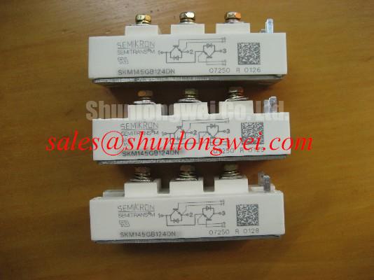
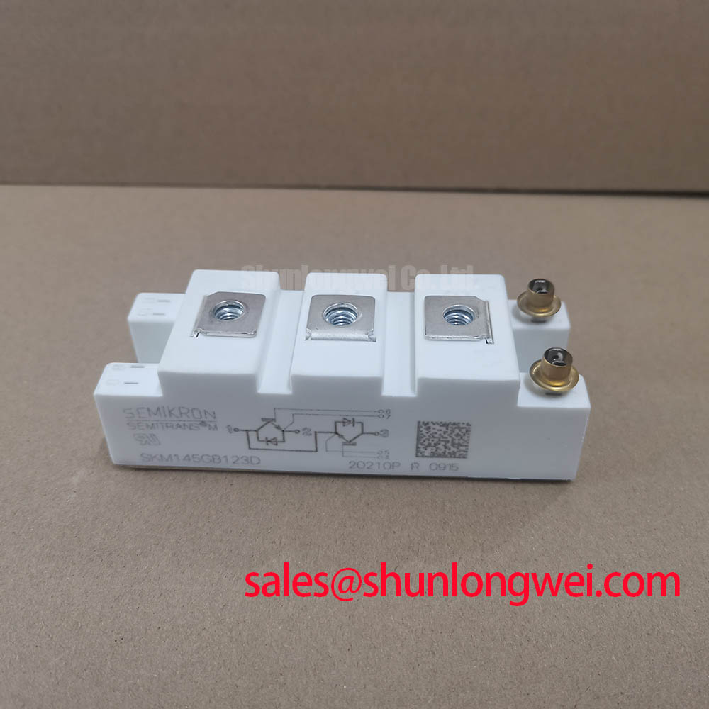
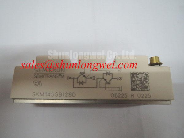
Start the bench check with the equipment isolated: confirm the nameplate rating, inspect the Semitrans housing for cracks or deformation, and compare the installed marking with the required SKM145GAL123D device before connecting a gate driver or DC link.
The supplied product data identifies this Semikron power module with an official voltage rating of 1200.0 V and an official current rating of 145.0 A. These are device identity parameters, not a complete operating guarantee for every switching frequency, overload profile, cooling arrangement, or pulse duration. The system designer should obtain the applicable Semikron documentation for switching energy, gate limits, thermal impedance, short circuit capability, isolation characteristics, and terminal assignment before releasing the module into service.
| Parameter | SKM145GAL123D information | Engineering use |
|---|---|---|
| Manufacturer | Semikron | Confirm the replacement family and mechanical interface |
| Rated voltage | 1200.0 V Official Specification | Compare with the measured DC link and switching overshoot |
| Rated current | 145.0 A Official Specification | Evaluate conduction, pulse duration, duty cycle, and cooling together |
| Product family | Semitrans Official Specification | Check mounting, terminal geometry, and thermal path |
For a pulsed inverter welder or medium-frequency induction heating supply, conduction loss and switching loss should be separated during the thermal review. Conduction loss follows the module’s actual collector-emitter behavior under the working current and temperature, while switching loss depends on bus voltage, gate resistance, current commutation, stray inductance, and the driver waveform. A multi-RC thermal model can be used as an Engineering Calculation to estimate the junction temperature response from the case temperature and time-varying loss. The model must use validated thermal impedance data for this exact device or approved family; generic resistance values should not be presented as factory specifications.
During field diagnostics, inspect the heatsink contact pattern, mounting flatness, thermal interface coverage, and signs of localized discoloration. A thermal camera can help compare phase legs under the same load, but its reading should be correlated with case temperature and electrical measurements. If one leg runs hotter, check current sharing, gate timing, diode commutation, busbar symmetry, and cooling flow before attributing the condition to the module itself.
For a compatible reference within the same product search path, engineers may review SKM75GAL063D as a separate Semikron device. It should not be treated as an automatic substitute because voltage, current, topology, terminal arrangement, switching behavior, and thermal requirements must all be checked against the original circuit.
Preventing Spurious Faults: Derating Guidelines and Mismatched Parameter Checks for SKM145GAL123D
When this 1200.0 V, 145.0 A Semitrans module is evaluated for an industrial inverter welder or medium-frequency induction heating power stage, derating is a system decision rather than a single percentage applied to the nameplate. The review should include DC-link tolerance, regenerative events, pulse repetition, ambient temperature, heatsink performance, airflow, switching frequency, and the measured voltage overshoot at the module terminals.
A positive temperature coefficient in the relevant static conduction characteristic can support current sharing between parallel devices under suitable operating conditions. That behavior does not remove the need for matched electrical paths. Unequal busbar resistance, different emitter inductance, or asymmetrical gate wiring can still produce unequal dynamic current during turn-on and turn-off. Designers should compare the actual gate-emitter waveforms at each module and verify collector-emitter overshoot with a properly rated differential probe.
Phase-angle conduction control introduces a different stress pattern from high-frequency hard switching. The device may experience uneven thermal cycling, line-frequency power variation, and changing commutation conditions as the control angle moves. Line-frequency ripple smoothing should therefore be assessed against the capacitor bank, control loop response, braking events, and the thermal time constant of the complete assembly. The correct capacitor value and control limits remain system-determined and require validation under the intended load profile.
RC snubbers can reduce high-frequency ringing when their values, placement, voltage rating, pulse capability, and damping behavior match the measured circuit. They should be selected from oscilloscope evidence rather than copied from another inverter. Excessive capacitance can increase switching loss, while insufficient damping may leave the IGBT exposed to repetitive transient stress. The Semikron-Danfoss SEMITRANS® Industry Standard IGBTs reference area provides useful family-level context, but the exact SKM145GAL123D limits must be confirmed from the applicable device documentation.
In a regenerative braking chopper, measure the braking resistor current and confirm that the resistor, switching device, clamp network, and control threshold share the energy burden as intended. A fault in the brake control loop may repeatedly drive the module toward its voltage or thermal boundary even when the average motor load appears normal. Check the DC-link waveform during acceleration, deceleration, and emergency stopping rather than relying only on a static multimeter reading.
Field Diagnostics & Commissioning: PCB Gate Loop Layout Symmetry in SKM145GAL123D Topologies
With power removed and the DC link safely discharged, compare the gate-to-emitter resistance and visible wiring of each phase leg against a known-good channel. Cold resistance is a screening measurement only. It can identify an open connection, an unexpected short, contamination, or a disconnected gate resistor, but it cannot prove that the semiconductor is healthy under switching conditions.
Where the installed module and driver provide an auxiliary emitter or Kelvin emitter connection, route that control return separately from the main high-current emitter path. The purpose is to prevent load-current voltage drop and common-emitter inductance from appearing directly in the gate-drive reference. The power return and control return should meet according to the validated driver topology, with the final arrangement determined by the module terminal definition and the gate-driver isolation scheme.
Keep parallel gate loops physically similar. Match conductor length, width, return geometry, resistor placement, and connector transitions so that each device receives a comparable gate waveform. Avoid routing sensitive gate traces alongside the collector bus, brake resistor wiring, or transformer conductors. Common-mode ground bounce may appear as a false gate signal, particularly when the control board and power assembly are connected by a long harness.
During commissioning, use an isolated differential measurement method suitable for the expected common-mode voltage. Observe the gate-emitter waveform at the module terminals, not only at the driver output. Look for ringing, delayed turn-off, abnormal plateau behavior, and differences between upper and lower switches. If a fault appears only at elevated bus voltage or load current, compare the signal path with a low-energy test condition before changing the gate resistor or adding a clamp.
Bootstrap supplies require special attention in half-bridge gate drivers. Confirm that the bootstrap capacitor receives adequate refresh time, that the charging path is compatible with the switching sequence, and that diode reverse-recovery current does not inject unacceptable disturbance into the control ground. The required capacitance, diode type, gate charge, duty cycle, and refresh interval must be calculated from the chosen driver and the verified module data. Do not assume that a bootstrap network from another Semikron assembly is suitable for this part.
The same discipline applies to negative gate turn-off bias. A negative bias may be considered where the driver, insulation system, gate-emitter rating, and switching environment support it, but the voltage is system-specific and must not be inferred from the product name. Shield the gate-drive reference from high-current commutation paths and verify the result during repetitive switching tests.
For the upstream rectifier or associated power stage, the SKM100GB063D may be reviewed as a separate complementary-stage reference. Its electrical and mechanical data require independent confirmation before any coordinated replacement decision.
Assembly Integrity & Layout Architecture: Mitigating Hard-Switching Transients in SKM145GAL123D Systems
Hard-switching reliability begins with the physical commutation loop. Minimize parasitic inductance in the DC-link capacitor, busbar, module terminals, and return path to suppress turn-off inductive overshoot. The acceptable peak voltage must be verified against the module’s documented switching and voltage limits using the actual operating temperature, current, and control timing.
Short-circuit protection should be coordinated with the gate driver, current sensor, desaturation or overcurrent circuit, blanking behavior, and fault reset logic. A type-I or type-II protection method may be appropriate depending on the topology, but the response time and soft turn-off profile must be validated against the exact module data. The often-used sub-ten-microsecond target should not be treated as an official SKM145GAL123D specification unless it is explicitly stated in the relevant manufacturer documentation.
A two-stage turn-off sequence can be evaluated as an Engineering Recommendation: first control the fault current transition to limit induced voltage, then complete gate discharge while maintaining the required isolation and driver stability. The timing, gate impedance, clamp action, and fault latch behavior are determined by the system. Test with a controlled current source or protected low-energy setup before applying the full DC link.
Mechanical assembly is equally important. Confirm that the heatsink surface, mounting hardware, electrical clearances, creepage path, busbar alignment, and terminal fasteners match the equipment design. Do not force a busbar into position to correct a dimensional mismatch; mechanical stress can transfer into the module housing and terminals. ⚠️ Field Alert: isolate and discharge the power stage before unplugging gate or auxiliary connections, and follow the mounting hardware manufacturer’s torque procedure rather than applying an assumed value.
Inspect the module after the first controlled run for abnormal heating, loose hardware, discoloration, and changes in gate waveform. Record DC-link voltage, phase current, switching frequency, case temperature, fault timing, and braking activity so that later comparisons use the same conditions. If repeated failures occur, preserve the driver board, gate resistors, snubber parts, busbar joints, and cooling interface for coordinated inspection.
Thermal interface and double-sided cooling concepts should be evaluated from the complete mechanical architecture, not inferred from the Semitrans name alone. The discussion in The Advanced Thermal Management Revolution can help frame that evaluation. For manufacturer-level product context, consult the Semikron-Danfoss Power Electronics & Modules Official Hub and verify the exact technical documentation for the device revision being integrated.