
Content last revised on October 29, 2026
Field Diagnostics and Commissioning: Pollution Degree 3 Creepage Distances in SKM195GB066D Topologies
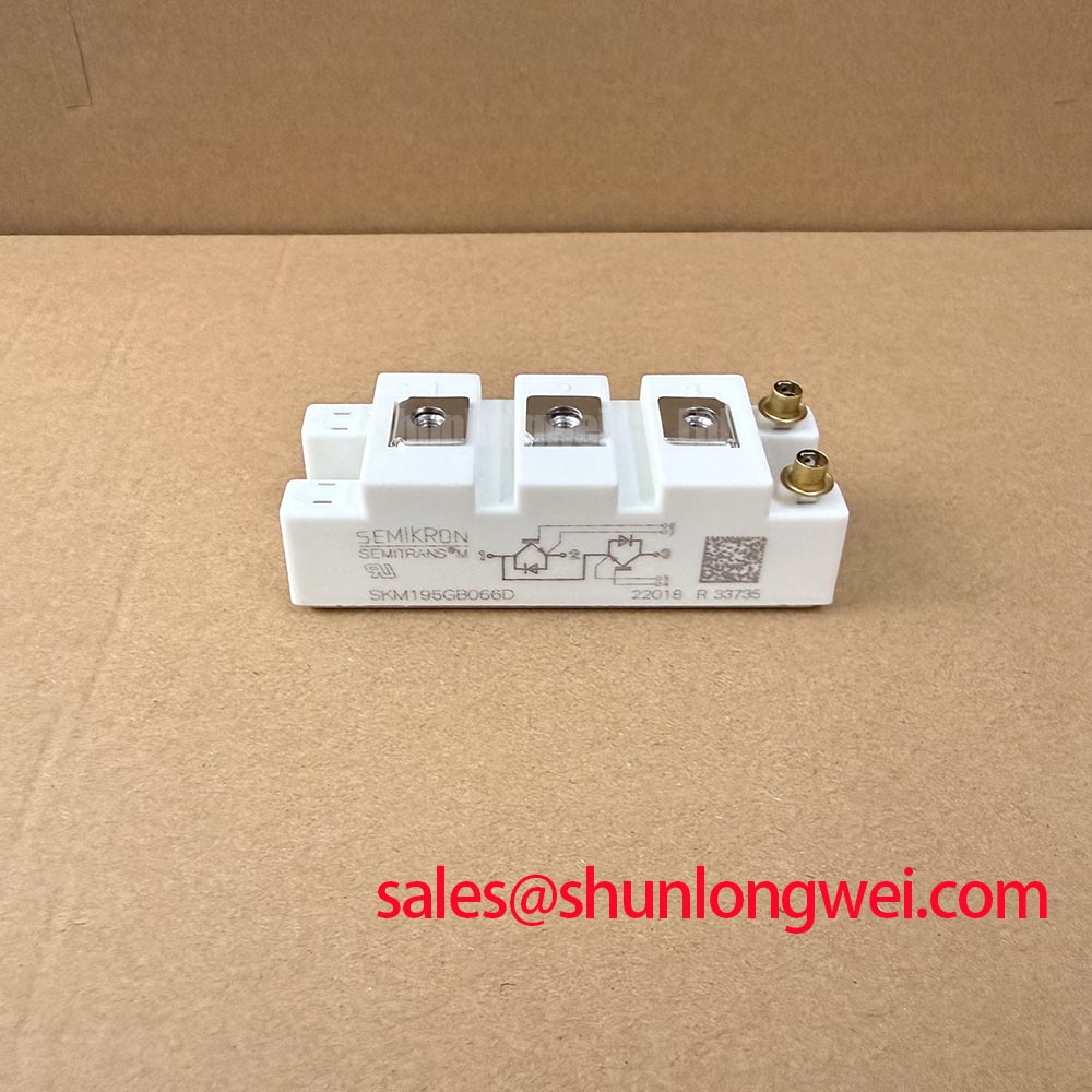
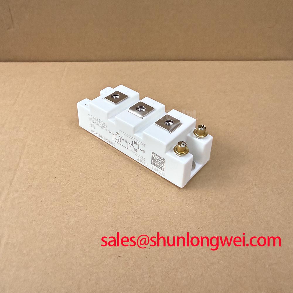
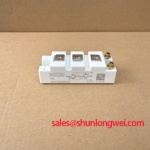
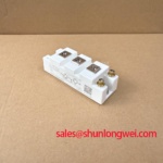
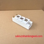
When a power cabinet has been exposed to conductive dust or repeated condensation, I isolate the inverter, discharge the DC link according to the equipment procedure, verify the absence of hazardous voltage, and inspect the terminal-to-baseplate insulation path before reconnecting control power. The SKM195GB066D is identified here as a Semikron Semitrans IGBT module with a specified voltage rating of 600.0 V and a rated collector current of 195.0 A under the datasheet-specified conditions. These ratings identify the device class; they do not replace the insulation coordination review of the complete assembly.
For Pollution Degree 3 environments, the practical concern is not only the nominal spacing visible around the terminals. Dust, salt deposits, moisture films, and residue from cleaning agents can reduce the effective surface path between live conductors and the baseplate. During commissioning, examine the terminal region, mounting surface, fastener heads, and nearby busbar supports as one continuous insulation system. Creepage should be assessed along the actual surface route, while clearance should be considered through the shortest air path. The final distances are determined by the equipment insulation system, working voltage, material group, pollution conditions, and applicable product standard.
A controlled insulation test can help identify contamination or a damaged isolation path. Use only the test voltage, duration, acceptance criterion, and terminal connections authorized by the module manufacturer and the equipment service procedure. A production insulation-withstand rating should not be treated as permission to apply the same voltage during field maintenance. Use an insulation tester suitable for power semiconductor assemblies, and disconnect sensitive gate-drive circuitry and other connected electronics as required by the approved procedure. The test arrangement must avoid applying damaging voltage across the semiconductor junctions or gate insulation.
Record the terminal connections, baseplate connection, test voltage, duration, and measured result. A lower reading that changes during the test may point toward surface contamination, trapped moisture, an external conductive path, or internal insulation damage. Clean and dry the surrounding assembly before repeating an authorized measurement, then compare the result with a known-good unit and the equipment maintenance record. Avoid interpreting one resistance value in isolation when the module remains connected to snubbers, voltage sensors, braking networks, or other external circuitry.
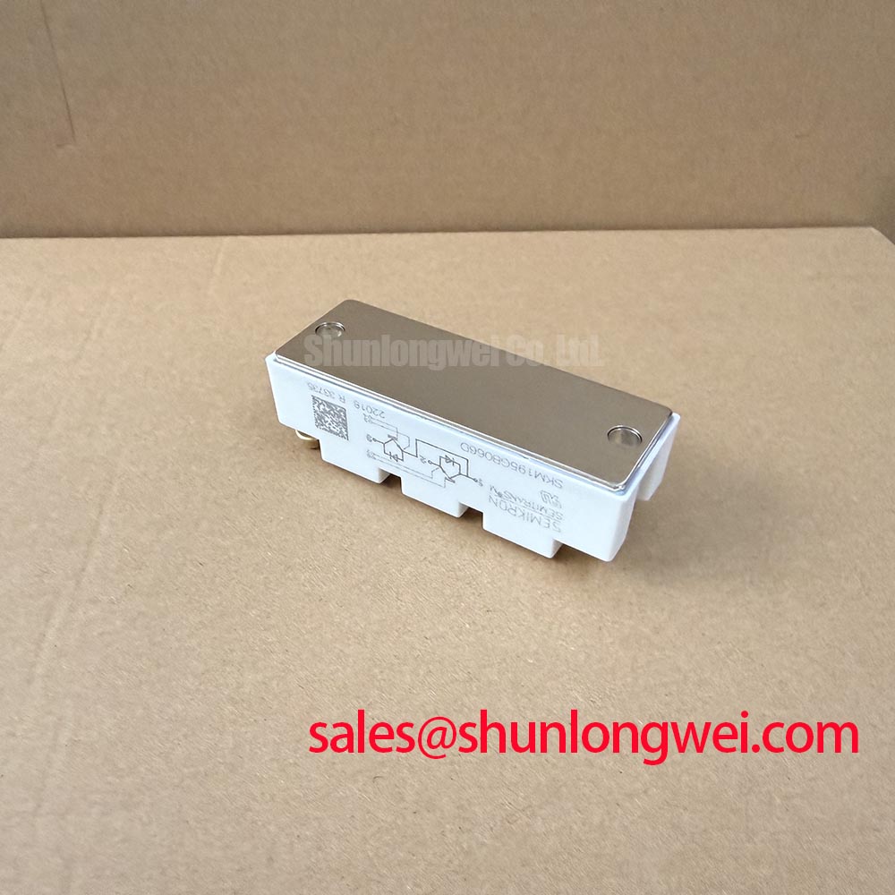
The DCB ceramic substrate forms part of the electrical isolation structure inside many power modules, but its condition cannot be confirmed by a visual inspection alone. Look for cracked mounting areas, abnormal discoloration, residue tracks, damaged terminal insulation, and signs that the module has been mechanically loaded during removal. If the insulation result remains abnormal after external contamination has been eliminated, remove the module from the wider circuit and follow the approved procedure for further testing under controlled conditions.
In an industrial inverter cabinet, route protective earth conductors and power conductors so that maintenance activity cannot bridge the isolation path with loose hardware or metal debris. The mounting surface should be clean and flat, and the baseplate should sit without rocking before the terminals are tightened. Where the original equipment documentation defines a creepage requirement, use that requirement rather than applying a generic clearance value. The Semikron-Danfoss reference for SEMITRANS® Industry Standard IGBTs provides useful product-family context, while the final cabinet design remains system-specific.
SKM195GB066D Operational Boundaries: Evaluating Torque Reaction Absorption and Preventing Terminal Stress
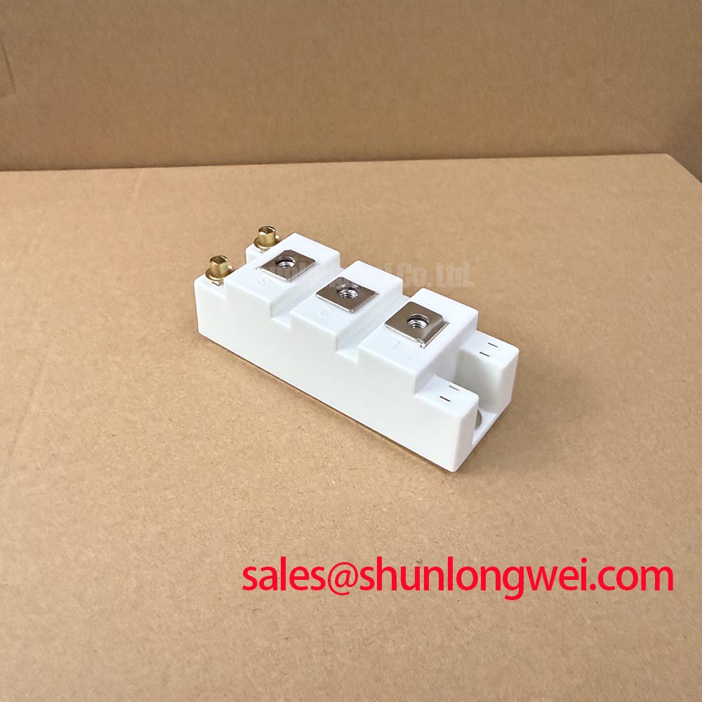
Mechanical loading at the main terminals should be controlled before the electrical performance of the replacement module is judged. During service work, inspect the screw thread engagement, washer seating, conductor alignment, and the amount of force required to bring the busbar into position. A busbar that is forced sideways into the terminal can transfer a levering load into internal copper joints, even when the final electrical connection appears tight.
Place the module on its correctly prepared heatsink or mounting surface before aligning the laminated busbar or cable lug. The conductor should approach the terminal without twisting. If the hole pattern does not align naturally, correct the external busbar position rather than using the terminal screw to pull the assembly into alignment. Check that washers remain centered and that no burr, paint, oxide, or foreign material prevents full contact. The tightening sequence should follow the equipment or module documentation, with the final torque applied using a calibrated tool.
⚠️ Maintenance Note: After thermal cycling or cabinet vibration, monitor contact temperature and verify the airflow path before treating a recurring power-stage fault as an electronic failure.
Torque reaction is also influenced by cable weight, unsupported busbars, and the movement of nearby cooling hardware. Support heavy conductors independently so that vibration does not repeatedly flex the module terminals. During inspection, look for fretting marks, displaced washers, darkened contact areas, or a terminal that no longer remains square to the conductor. These findings do not establish a single failure cause, but they justify a closer mechanical review before energization.
Fast semiconductor fuse coordination must be evaluated against the actual protection network rather than selected from current rating alone. The fuse clearing characteristic, available fault current, circuit inductance, DC-link voltage, and any applicable published surge and short-circuit limits all influence the result. Compare the fuse clearing I2t with the semiconductor protection requirement used by the equipment designer where applicable; I2t alone does not establish IGBT short-circuit protection. Include the effects of wiring and commutation inductance. A fuse that interrupts rapidly may still allow a damaging voltage transient if the physical current loop is poorly arranged.
During a controlled fault-protection review, verify that the fuse, gate-drive shutdown, contactor sequence, and DC-link discharge path operate as a coordinated system. Record the gate signal, collector-emitter voltage, phase current, and protection timing with probes rated for the measured environment. The aim is to confirm that the protection action occurs inside the safe operating conditions established for the module and the wider converter. Do not infer protection adequacy from a successful no-load startup.
For a field replacement, the electrically compatible device selected by the original equipment designer should remain the reference. The related SKM195GB126D may be reviewed as a separate Semikron device for compatibility comparison, but terminal arrangement, voltage class, current capability, gate-drive behavior, thermal interface, and protection settings must be checked against the equipment documentation before any substitution is considered.
SKM195GB066D Thermal-Electrical Optimization: Thermal Stress Alleviation in Bidirectional Power-Flow Tuning
In commercial string inverter and micro-grid energy storage equipment, thermal stress often follows the power-flow schedule rather than a simple continuous-load profile. Battery charging, battery discharge, photovoltaic power variation, and grid-support commands can move current through the converter in changing directions. When evaluating the SKM195GB066D, map the four-quadrant operating sequence against junction-temperature indicators, heatsink temperature, switching commands, and phase-current balance.
The specified 600.0 V voltage rating and 195.0 A current rating under the datasheet-specified conditions are essential selection data, but the thermal result depends on switching frequency, conduction duty, modulation strategy, cooling performance, gate-drive timing, and the converter’s actual load profile. Treat the ratings as device limits subject to their specified conditions and calculate the installed operating condition from the applicable Semikron documentation and the system thermal model. A module that performs acceptably during a short commissioning run may experience a different stress pattern during repeated peak shaving.
Start the thermal review with the physical heat path. Remove dust from the heatsink and fan intake, inspect the interface material for pump-out or dry areas, and confirm that the mounting surface remains flat. Check that the module is seated evenly and that the cooling airflow is not bypassing the fin area. Thermal interface material should be applied according to the module and heatsink supplier’s installation instructions; excessive material can increase interface resistance, while insufficient coverage can leave localized hot spots.
Measure temperature at comparable points during charge and discharge transitions rather than recording only a cabinet average. A rising contact or heatsink temperature with stable ambient conditions may indicate a change in interface quality, airflow, current sharing, or switching behavior. Compare phases and operating directions. If one phase departs from the others, inspect its gate signal, current sensor path, busbar connection, and freewheeling path before changing the control parameters.
Reverse recovery behavior in the freewheeling diode path can affect both switching loss and radiated EMI. The relevant concern is the shape and softness of the reverse-recovery current, together with loop inductance, gate resistance, commutation timing, and the physical placement of the DC-link capacitor. A sharper recovery event can increase voltage ringing and common-mode excitation, while excessive damping can increase switching loss. The correct balance must be established through measured waveforms and thermal results rather than assumed from the module’s current label.
Dead-time settings also require bench verification. Insufficient dead time can permit cross-conduction during a switching transition, while excessive dead time can increase diode conduction and recovery stress. Review the actual high-side and low-side gate waveforms at the module terminals, including propagation delay, Miller behavior, shutdown response, and the effect of the gate-drive supply under load. Any microsecond-scale buffer or interlock should be selected from the driver, switching speed, and protection architecture used in the converter, then verified during double-pulse and system-level tests.
Long motor or cabinet cables can behave as transmission paths and reflect fast voltage edges back toward the switching stage. Although commercial string inverters and energy storage converters do not always use motor outputs, the same principle applies to long external conductors between the power stage, filter, and load. Minimize the high di/dt loop area, keep the commutation path compact, and evaluate peak voltage at the module terminals with a properly compensated differential probe. Filtering, damping, and cable treatment should be selected by the system engineer after the measured waveform, insulation coordination, and thermal penalty are understood.
Layered busbars can reduce stray inductance when their forward and return paths are closely coupled, but the practical benefit depends on the complete mechanical stack-up. Keep the capacitor-to-module path short and direct, avoid unnecessary changes in conductor width, and prevent control wiring from running parallel to high-current switching paths. During switching tests, verify the measured collector-emitter peak against the module’s applicable voltage limits as well as the DC-link operating range and the transient limits specified for the complete design.
For auxiliary rectification or a coordinated front-end stage, engineers may review the related SKM145GB174DN as a separate device in the wider power topology. Its suitability cannot be inferred from the SKM195GB066D ratings. The gate-drive supply, diode behavior, fuse coordination, thermal path, and terminal configuration must each be assessed in the intended circuit.
The broader switching and reliability principles are also discussed in the technical guide on IGBTs. For maintenance teams, the actionable routine remains practical: keep the heatsink clean, inspect the interface material during scheduled service, check terminal condition after thermal cycling, and trend contact temperature while the inverter moves through its normal bidirectional power profile.