Content last revised on October 5, 2026
SKM145GB174DN Circuit Protection and Reliability: Symmetrical Busbar and Gate Paths
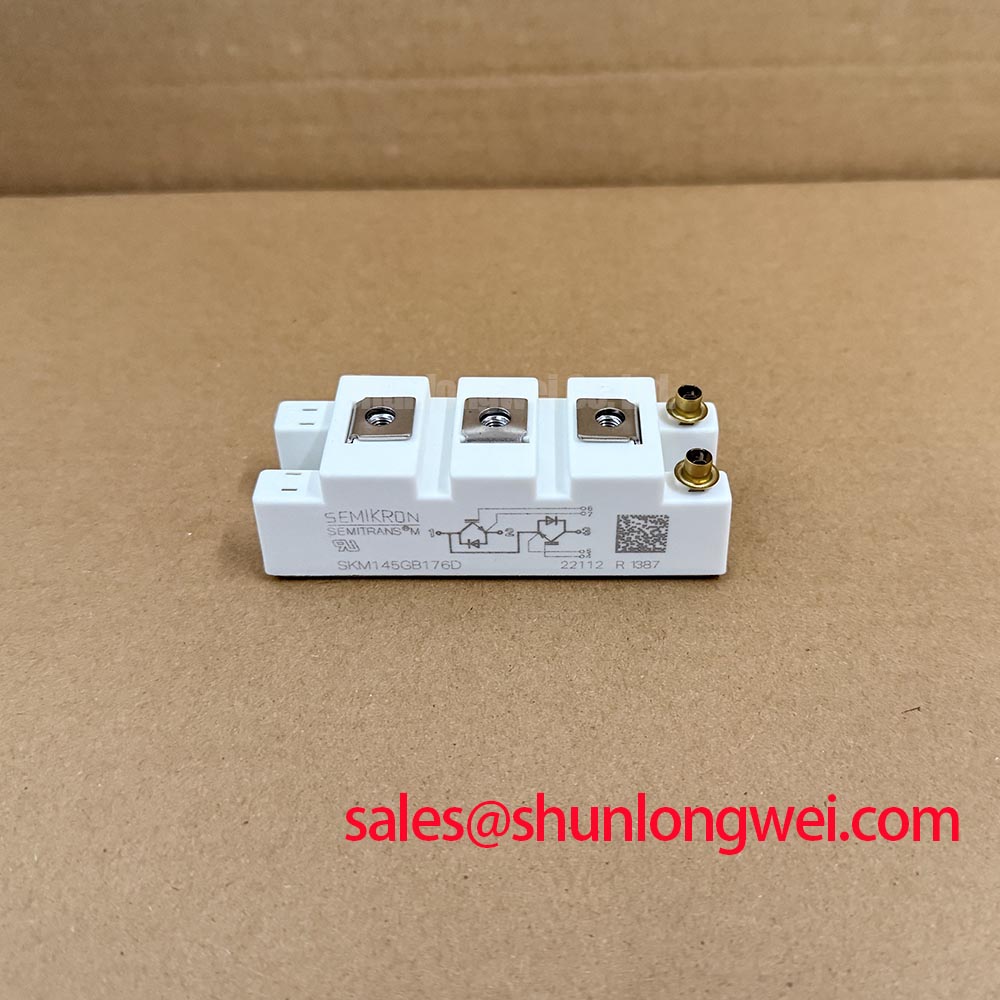
With the DC link isolated and discharged, check cold terminal resistance and inspect the power connections before evaluating SKM145GB174DN for an in-place repair. Record the readings against the equipment schematic and a known-good assembly where one is available; a resistance reading alone cannot establish that an IGBT module is fit for service. The supplied manufacturer ratings identify this Semikron SEMITRANS module as a 1700 V, 145 A device (Official Specification). Confirm the installed module’s terminal arrangement, mechanical fit and operating conditions against its original documentation before treating those ratings as evidence of compatibility.
When parallel current paths are involved, start at the physical connections rather than assuming identical modules will share current equally. Trace each busbar branch from the DC link to its module terminals, looking for unequal path lengths, different joint constructions, displaced insulation and signs of heating at bolted interfaces. Equal-looking copper is not necessarily electrically symmetrical: joint condition and return-path geometry also affect the impedance encountered during switching. As a Design Consideration, keep corresponding power paths comparable to reduce differences in voltage overshoot and dynamic current sharing, then verify the result at the operating conditions set by the system designer.
The positive temperature coefficient of on-state collector-emitter voltage is often discussed as an aid to static sharing between suitably matched IGBTs. Do not assign a coefficient or a guaranteed sharing benefit to SKM145GB174DN without the applicable manufacturer curves and test conditions. Static behavior also does not resolve a mismatch during turn-on or turn-off. Follow both gate-drive routes back to the driver, checking connector seating, conductor routing and return-path symmetry. A difference in measured gate waveforms calls for investigation of the driver and interconnect as well as the module.
Protection review belongs alongside that inspection. Compare the installed gate-drive, overcurrent detection and fault-handling arrangement with the equipment schematic before energizing a replacement. Minimize parasitic power-loop inductance to limit turn-off overshoot, but determine acceptable layout and protection settings through switching measurements against the actual DC-link voltage and the module’s rated boundary. The Precision Gate Drive Design guide provides background for that driver-level review; it does not replace the original equipment settings.
For a procurement cross-check, SKM75GB07E3 can be examined as another Semikron module listing, not assumed to be an electrical or mechanical substitute. Compare voltage and current ratings, terminal map, package fit, gate-drive requirements and thermal conditions individually. The Semikron-Danfoss SEMITRANS product information gives family-level context, while the exact installed-part documentation governs the repair decision.
Field Diagnostics and Commissioning: DC-Bus Headroom in SKM145GB174DN Topologies
Before reconnecting the DC bus, identify every power and gate terminal from the original module drawing and the equipment wiring record. Do not infer the pinout from a similar-looking SEMITRANS housing. With the assembly de-energized, compare the suspected module’s cold measurements with the service procedure and inspect the surrounding snubber, busbar insulation and gate-drive connections. An abnormal reading may reflect a path through connected circuitry; isolate the relevant connection before attributing it to the module.
The 1700 V rating is an Official Specification, not a statement that a system may operate continuously at any chosen fraction of that value. For commissioning, capture the DC-bus level and switching peaks under the equipment’s defined test conditions. Check the highest observed collector-emitter stress against the rated boundary, allowing for measurement uncertainty and the operating cases specified by the system designer. If the peak is unexpectedly high, examine the busbar return path, switching behavior and protection circuit before changing a gate-drive setting.
As a Design Consideration, elevated operating altitude and DC-bus voltage can warrant a separate reliability assessment. The supplied product data does not provide a site-specific terrestrial-neutron exposure model, single-event-burnout rate or FIT value for SKM145GB174DN; no defensible failure-rate calculation follows from its voltage rating alone. An altitude-related voltage decision would require relevant manufacturer guidance, site conditions and the system’s reliability criteria. Keep that assessment distinct from the immediately measurable switching-voltage check.
Inspect creepage and clearance along the assembled insulation path, including nearby busbars and any displaced barriers, against the equipment’s applicable design documentation. Check that fasteners and supports are seated as specified and that vibration has not loosened a joint or shifted a conductor toward an adjacent potential. Field Alert: Tighten busbar and mounting connections to the applicable hardware specification, not to a torque inferred from the module’s appearance. After reassembly, document the connection inspection and repeat the equipment’s approved pre-energization checks.
SKM145GB174DN Thermal-Electrical Optimization in Bidirectional Power Conversion
A centralized battery energy storage PCS is one possible compatibility-evaluation setting for this module, not an application guaranteed by its nameplate. In a bidirectional converter, charging and discharging operating points can place different current, switching and cooling demands on the installed power stage. Map those operating points against the original converter schematic before assessing SKM145GB174DN. Its 145 A current rating is an Official Specification; the supplied data does not establish the temperature, cooling arrangement or waveform conditions needed to turn that figure into a permissible PCS operating current.
Start thermal troubleshooting with measurements the site can repeat. Review the cooling-path condition, mounting contact, airflow or liquid-cooling status as applicable, and temperature-sensor history during comparable operating periods. A rising case-area temperature may be consistent with several issues, including altered cooling, increased electrical loss or poor contact. It is not, by itself, a diagnosis of a module defect. Correlate temperature trends with DC-bus voltage, phase current and switching records before deciding which part of the power stage needs closer examination.
When a converter alternates between battery charging and discharge, repeated changes in dissipated power can produce thermal cycling. As a Design Consideration, assess the magnitude and timing of those changes against the manufacturer’s applicable thermal information and the converter’s measured duty profile. Do not convert a peak-shaving schedule into a module-life estimate without validated thermal and lifetime data. For a replacement evaluation, compare the original cooling interface and control strategy as carefully as the electrical ratings; either can affect the measured temperature response.
Inspect the mounting surface for contamination or damage and follow the equipment procedure for the thermal interface material. Avoid assuming that more compound improves heat transfer: the required application and fastening sequence depend on the mating surfaces and hardware specification. The Semikron-Danfoss power modules catalog is useful for locating manufacturer family information, but product-family material should not be treated as a mounting instruction for an undocumented assembly.
Transient Dynamics and Electrical Design: Checking Pulsed Thermal Stress
A brief overload cannot be judged from the 145 A rating alone. First establish what the equipment actually commanded: capture current, pulse duration, DC-bus behavior and the cooling condition at the event. Compare those records with the original design limits and the exact module’s applicable transient thermal data if available. The supplied specifications do not include a transient thermal-impedance curve, a multi-RC model or a maximum junction-temperature value, so a numerical peak-junction-temperature margin cannot be stated responsibly here.
The engineering principle is to compare loss energy deposited during the pulse with the module’s time-dependent thermal response, then account for the temperature present before the pulse. That comparison becomes an Engineering Calculation only when the appropriate manufacturer thermal model, loss data and measured operating waveform are available. A steady case-temperature reading can miss a short junction-temperature excursion; conversely, a recorded current spike does not prove that a thermal limit was exceeded. Preserve the waveform and its timing before resetting a drive fault that may contain useful evidence.
During controlled recommissioning, keep voltage and current probes referenced according to the approved test procedure and compare switching traces with a known-good phase where the converter permits it. Ringing, asymmetric transitions or a temperature trend that differs between comparable paths should prompt checks of the gate circuit, busbar joints, sensing and cooling contact. Treat each observation as a lead rather than a single-cause verdict. Final pulse limits and protection thresholds belong to the system design and must be verified under its intended operating conditions.