Content last revised on October 7, 2026
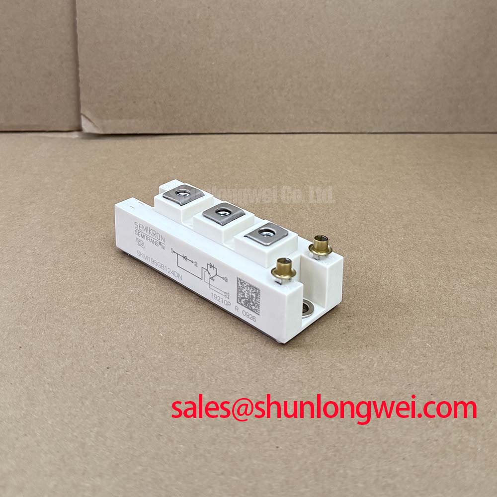
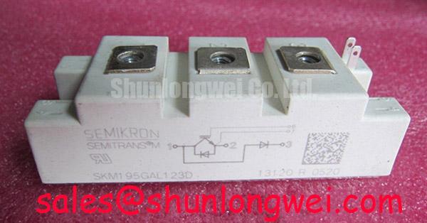
SKM195GB126D Semikron 1200V 195A IGBT Module
| Manufacturer | Semikron |
| Product model | SKM195GB126D |
| Product category | IGBT Module |
| Rated voltage | 1200.0 V |
| Rated current | 195.0 A |
| Package | Semitrans |
Before installing the replacement, isolate the drive, discharge the DC link, and compare the module marking with the equipment documentation. For SKM195GB126D, the confirmed manufacturer and product data are Semikron, 1200.0 V rated voltage, 195.0 A rated current, and a Semitrans package. These values identify the component category and electrical class, but they do not replace verification of the original gate-drive, cooling, switching-frequency, and protection requirements.
Cosmic Ray Robustness: Voltage Derating Curves across 2000m to 4000m Altitudes
For a heavy-duty variable-frequency AC motor drive, high-altitude evaluation should begin with the actual DC-link voltage waveform rather than with the nominal inverter rating. At elevations above approximately 2000 m, atmospheric conditions, insulation coordination, cooling capability, and terrestrial radiation exposure can all become relevant design considerations. The available product information confirms a 1200.0 V voltage rating for SKM195GB126D, but it does not provide a manufacturer-approved cosmic-ray FIT curve, Single Event Burnout data set, or altitude derating table.
SEB assessment therefore requires system-specific evidence. Record the highest repetitive DC-link voltage, turn-off overshoot, regenerative events, and braking transients with appropriately rated measurement equipment. The measured peak should be compared with the device rating and the applicable system safety requirements. A simple nominal-voltage comparison is insufficient when long motor cables, weak clamping, or uncontrolled regeneration produce short-duration voltage excursions.
Engineers evaluating installations between 2000 m and 4000 m should request the relevant manufacturer qualification information where the application risk requires a quantified FIT estimate. Without an authoritative radiation test report or reliability model, assigning a numerical SEB failure rate would be misleading. The practical maintenance approach is to trend DC-link peak voltage, inspect snubber and clamp components, and check whether repeated high-energy switching events are concentrated at particular operating speeds or load transitions.
Clearance and creepage should be reviewed against the applicable insulation-coordination standard and the complete drive construction. The module alone cannot be declared compliant with the full enclosure or inverter insulation system. The Field Engineer’s Handbook can be used as a practical reference when organizing waveform capture, failure inspection, and controlled replacement testing.
DC-Link Capacitance Bank Layout and Low-ESL Busbar Interconnection Techniques
Installers should inspect the complete commutation loop from the DC-link capacitor bank through the IGBT module and back to the capacitor terminals. Stray inductance in this loop converts switching current change into voltage overshoot. In engineering terms, the peak voltage rises with both loop inductance and switching current slew rate, so a module carrying 195.0 A must not be evaluated from current rating alone.
A symmetrical laminated or closely coupled busbar arrangement is a design consideration for reducing loop area and stray inductance. The capacitor bank should be positioned according to the actual switching topology, with short, mechanically secure connections and no unnecessary conductor loops. Designers should verify the result using a suitable differential voltage probe at the module terminals, because a remote DC-link measurement can hide the local overshoot seen by the semiconductor.
Snubber selection must follow the measured switching waveform, capacitor parasitics, pulse energy, repetition rate, and thermal environment. The SKM195GB126D data supplied for this page does not specify a snubber capacitance, allowable commutation inductance, desaturation delay, or short-circuit protection timing. Those values must come from the applicable device documentation and the gate-driver design. A desaturation circuit should be evaluated for detection delay, blanking behavior, fault propagation, and controlled turn-off performance rather than treated as a universal plug-in protection function.
Two-stage soft turn-off is often considered in high-energy inverter protection because abruptly interrupting a large fault current can create a severe collector-emitter transient. Whether that method is suitable depends on the gate driver, current path, clamp network, and measured fault waveform. The Semikron-Danfoss SKiiP® Technology page provides useful industry context for integrated power semiconductor and drive-system concepts, but it should not be treated as a specification for this individual module.
For a front-end arrangement using controlled or phase-controlled rectification, check conduction angle, DC-link ripple, braking regeneration, and input-current distortion together. Harmonic suppression is a system responsibility involving the rectifier topology, line impedance, filters, control strategy, and compliance target. A replacement IGBT module does not independently establish compliance with grid-harmonic or EMC requirements.
Auxiliary Emitter Return Trace Separation for Rapid dv/dt Transients
Gate-drive behavior should be checked at the module terminals and at the driver reference point. In a high-current inverter, the main emitter current path can develop a transient voltage that is different from the local gate-driver reference. If the auxiliary emitter return shares a high-current path, mutual coupling can alter the apparent gate-emitter voltage and contribute to ringing, unintended gate movement, or inconsistent turn-off behavior.
The recommended engineering principle is to keep the gate-drive return physically separate from the main power-current return for as much of the layout as the module interface permits. The final routing, conductor width, spacing, connector arrangement, and shielding method remain system-dependent. Designers should verify gate-emitter voltage directly during turn-on, turn-off, short-circuit interruption, and regenerative operation.
When troubleshooting a drive that repeatedly reports overcurrent or gate-driver faults, compare the suspected phase with a known-good phase under controlled conditions. Inspect connector seating, solder joints, auxiliary return continuity, gate resistor condition, and driver supply stability. An abnormal waveform may indicate parasitic coupling, an unstable driver, excessive overshoot, or a damaged power path; it should not be assigned to one cause without oscilloscope evidence.
⚠️ Field Alert: Disconnect the DC link and verify stored energy has decayed before removing the module or gate-drive connector; never insert or remove control wiring on an energized inverter.
The SKM100GB124D may be reviewed as a separate Semikron reference device during a comparative repair assessment, but voltage, current, pin arrangement, thermal behavior, and gate-drive compatibility must be confirmed independently before any substitution is considered.
Thermal Time Constants and Peak Junction Temperature Margin Calculation
Thermal inspection should start with the cooling assembly. Remove accumulated dust from the heatsink, inspect fan operation or liquid-cooling flow where applicable, and check for uneven contact between the Semitrans base and the heatsink. The official information available here confirms the package type and electrical ratings, but it does not provide the transient thermal impedance curve, junction-to-case resistance, maximum junction temperature, overload duration, or case-temperature limit for this specific order code.
For a pulsed overload, the relevant temperature is not determined by steady-state current alone. The engineer should combine measured case temperature, pulse duration, repetition interval, switching loss, conduction loss, and the manufacturer’s transient thermal impedance data. A multi-stage RC thermal model can then estimate the junction response, provided each thermal parameter is taken from an authoritative source rather than inferred from the current rating.
During commissioning, capture the case-temperature trend at representative motor loads and acceleration profiles. Pay particular attention to low-speed operation, repeated braking, high ambient temperature, and restricted cabinet airflow. Long motor cables can also produce reflected-wave voltage stress at the motor terminals, which may increase inverter switching stress depending on cable construction, termination, switching speed, and installation length. Filtering and output-reactor decisions should be based on measured waveform behavior and the drive manufacturer’s requirements.
Thermal compound should be applied according to the heatsink and interface-material manufacturer’s process instructions. Excess material, uneven clamping, contamination, or a warped mounting surface can increase interface thermal resistance. Fastener tightening should follow the module manufacturer’s mechanical documentation and the actual heatsink assembly specification rather than a generic torque assumption.
In a DC-link or rectifier service inspection, also check capacitor ripple current, busbar discoloration, terminal heating, and phase balance. The SKM100GB063D can be considered as a separately documented Semikron device in a related rectifier or complementary-stage review, while its electrical and mechanical compatibility must be established from its own documentation.
For installation standards and contactor or motor-starter coordination, consult the applicable system requirements and the IEC 60947-4-1 publication. That standard applies to relevant equipment categories and does not constitute an individual certification claim for SKM195GB126D. Before energizing a repaired heavy-duty VFD, verify gate-drive polarity, phase sequence, insulation condition, cooling performance, DC-link precharge, protection response, and switching waveforms under controlled load.