Content last revised on September 28, 2026
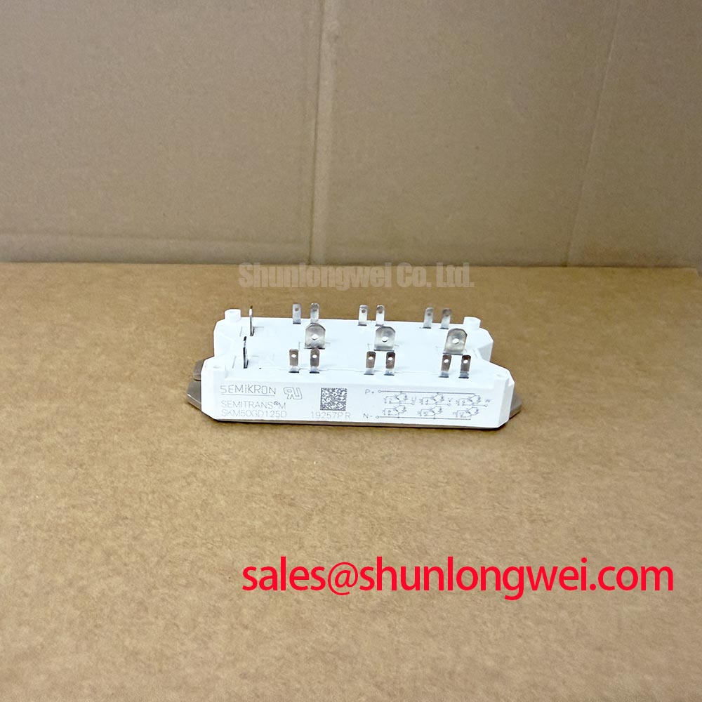
SKM50GB128D Semikron 1200V 50A IGBT Module
| Parameter | Value | Classification |
|---|---|---|
| Product model | SKM50GB128D | Official product identification |
| Manufacturer | Semikron | Official product identification |
| Rated voltage | 1200.0 V | Official specification |
| Rated current | 50.0 A | Official specification |
| Package | Semitrans | Official specification |
Begin a service inspection by isolating the DC link, documenting the original wiring, and checking the module marking against the equipment record before removing the power connections. The SKM50GB128D is a Semikron IGBT module specified at 1200.0 V and 50.0 A, with a Semitrans package. These are the confirmed product data available for initial replacement screening; switching frequency, gate charge, saturation voltage, thermal resistance, isolation rating, and terminal arrangement should be verified from the applicable manufacturer documentation before circuit approval.
Preventing Spurious Faults: Calculating Failures-in-Time Rates in High Altitude Guidelines for SKM50GB128D
Single Event Burnout and neutron related FIT analysis require device specific radiation data, mission altitude, operating voltage, exposure duration, and a recognized reliability model. No numerical FIT rate, SEB threshold, or altitude derating value should be assigned to this module without an authoritative Semikron document or a qualified reliability study. The 1200.0 V rating is an official electrical boundary, not a complete guarantee against every transient or cosmic radiation condition.
As a Design Consideration, engineers evaluating commercial string inverters or microgrid storage converters at elevated sites should establish the actual DC bus range, switching overshoot, repetitive transient profile, and environmental operating conditions. The validation plan should compare measured peak collector emitter voltage with the applicable device limits during startup, normal power transfer, regenerative braking, and fault interruption. A double pulse test can reveal layout related overshoot that a low bandwidth service measurement may miss.
Clearance, creepage, insulation coordination, and enclosure contamination control remain system responsibilities. The appropriate values depend on working voltage, pollution environment, altitude, material group, and the governing safety standard. Field troubleshooting should begin with a visual inspection, isolation resistance checks performed with suitable procedures, and oscilloscope verification of the gate emitter and collector emitter waveforms against a known good phase leg. A sporadic overcurrent alarm may involve control timing, current sensing, driver supply behavior, commutation layout, or an overstressed power device, so the measured signal path should be reviewed before assigning a single cause.
For semiconductor background, engineers can consult the Semikron-Danfoss SEMITRANS® Industry Standard IGBTs product information. This external reference helps place the package family in context but does not replace the product specific data required for a release decision.
Assembly Integrity & Layout Architecture: Managing High C Rate Battery Cycling for SKM50GB128D
A bidirectional battery inverter can move power into or out of the DC link, creating repeated transitions between rectification, inversion, charging, discharging, and regenerative energy absorption. During high C rate peak shaving, the module selection should be checked against the complete current waveform rather than a single average value. The official 50.0 A rating must be interpreted with the thermal conditions, switching operation, current duration, and applicable datasheet curves.
As an Engineering Recommendation, designers should map junction temperature movement and case temperature response across the real battery duty cycle. Repeated thermal swings can influence solder joints, interfaces, busbar connections, and the surrounding cooling assembly even when instantaneous electrical values appear acceptable. A thermal camera can support commissioning checks, but temperature measurements should be correlated with electrical loading and sensor placement.
When parallel modules are considered, static current sharing depends on matched electrical paths, thermal symmetry, device characteristics, and control timing. IGBT saturation voltage generally has a positive temperature relationship that can support stabilizing behavior in parallel operation, but this should not be treated as a guaranteed sharing mechanism for this specific part without the relevant curves. Equal busbar impedance and comparable cooling conditions are required before current balance can be judged.
The DC link layout should minimize the commutation loop area and keep parallel current paths physically symmetrical. Designers should verify turn off overshoot at the module terminals during the complete battery charge and discharge sequence, including transitions caused by regenerative braking choppers and braking resistor energy absorption. The measured peak margin against the DC link voltage remains a system design decision.
For a capacity comparison exercise, the SKM100GB063D may be reviewed as a separate Semikron reference model. It should not be treated as a drop in substitute until voltage, current, topology, terminal geometry, gate drive requirements, thermal behavior, and mechanical mounting have been checked.
Assembly Integrity & Layout Architecture: Galvanic Gate Drive Isolation for SKM50GB128D
The gate driver interface must preserve galvanic separation between the control domain and the switching power domain. The isolation barrier, driver supply arrangement, gate return path, and common mode transient performance are properties of the complete driver assembly, not confirmed specifications of the IGBT module alone. Claims such as reinforced isolation above 5 kV or CMTI above 100 kV per microsecond require supporting data for the selected optocoupler or digital isolator and its implementation.
As a Design Consideration, the isolated driver should be evaluated under the same collector voltage slew rate, gate current, and commutation conditions expected in the inverter. The test should monitor both the intended gate waveform and any unwanted pulse on the inactive switch. Gate loop conductors should be kept compact, with the power return and signal reference arranged to reduce common impedance coupling. The exact gate resistance, supply voltage, clamp network, and active Miller control settings must be selected from the applicable gate drive design and device documentation.
During a fault investigation, compare the isolated driver output with the controller command at the same time base. Check driver supply droop, isolation barrier behavior, gate emitter reference movement, desaturation or overcurrent feedback, and the timing of shutdown signals. An unexpected pulse may indicate common mode coupling, propagation delay interaction, grounding geometry, or control logic behavior; oscilloscope evidence should distinguish these possibilities before a component is replaced.
Pro Tip: Disconnect power before inserting or removing gate driver and module connections, then verify the driver reference wiring against the original phase leg documentation.
The practical design principles are collected in Precision Gate Drive Design, which can support review of gate loop geometry, Miller control, isolation strategy, and switching test methods.
SKM50GB128D Thermal Electrical Optimization: Multi Module Parallel Current Sharing
Parallel operation should start with a topology review rather than a simple current multiplication. Each module must experience comparable collector path impedance, emitter return impedance, gate loop inductance, cooling conditions, and command timing. A symmetrical laminated busbar arrangement can reduce unequal commutation behavior, while matched gate wiring helps limit dynamic imbalance. The final arrangement should be validated with current probes and synchronized gate waveform measurements.
For steady state sharing, measure the current in each branch over the expected load range and record case temperature at equivalent locations. The positive temperature behavior commonly associated with IGBT saturation voltage can contribute to passive balancing, but it does not remove the need to verify transient sharing, short circuit response, and thermal coupling for the selected module and operating point.
When a commercial string inverter or microgrid storage converter includes regenerative braking or a braking resistor chopper, review the energy path during fault recovery and rapid power reversal. The module must be assessed within the complete switching cell, including the DC link capacitor, clamp network, busbar, driver, current sensor, and cooling assembly. Minimize parasitic loop inductance to suppress turn off voltage overshoot, then verify the resulting peak voltage and current margins through controlled switching tests.
A replacement inspection should document terminal orientation, mechanical contact, thermal interface condition, fastener loading, and the original gate driver settings. Any change to the module package or electrical topology requires renewed checks of insulation coordination, control timing, protection response, and thermal performance before the equipment returns to service.