



Content last revised on September 16, 2026
Benchtop Waveform Tuning: Mitigating Stress via ITSM Safety Derating on SKT300/12
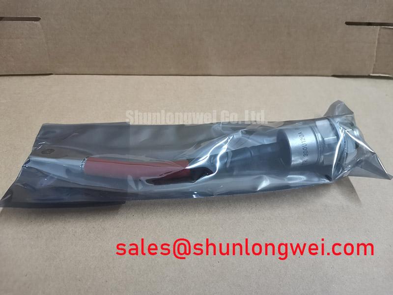
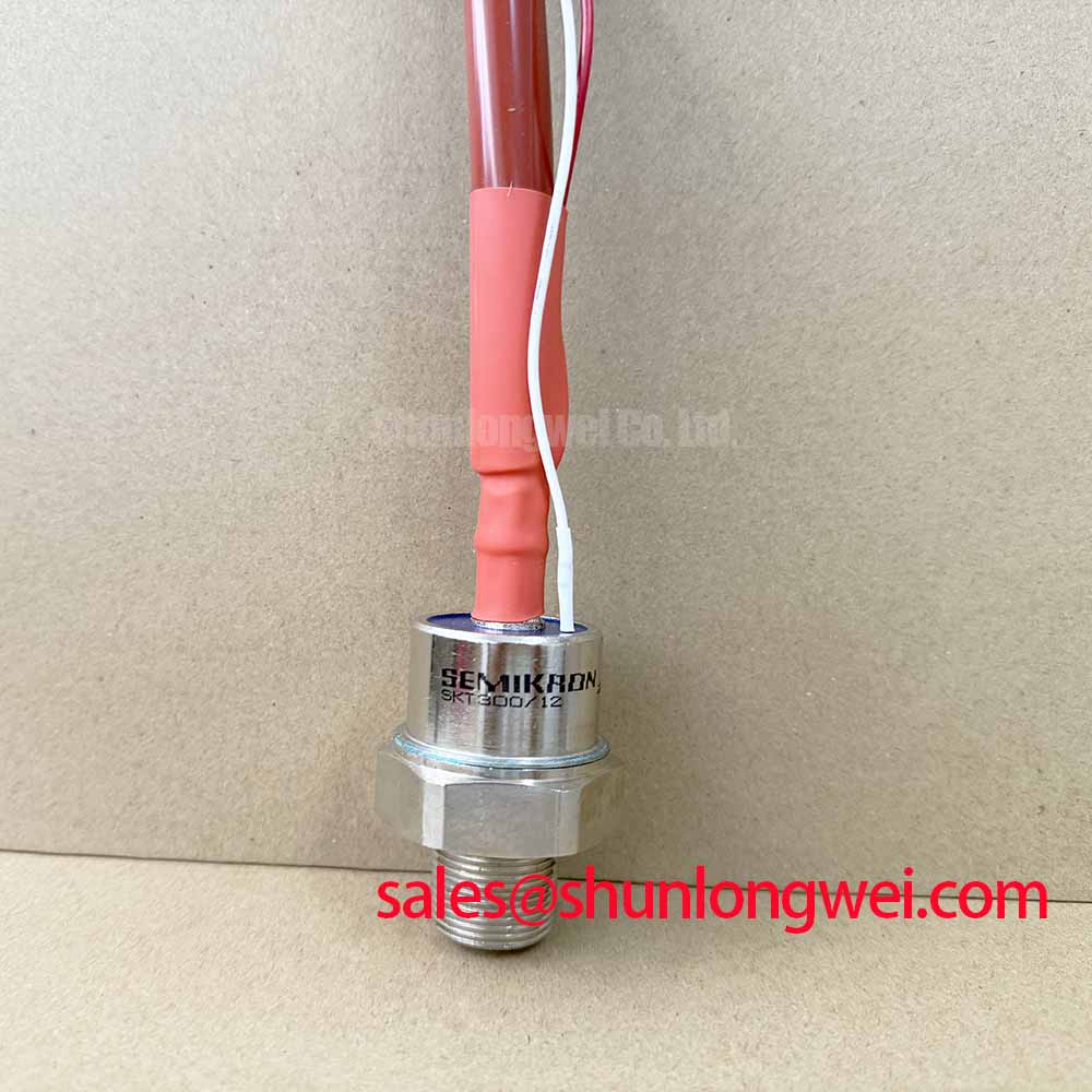
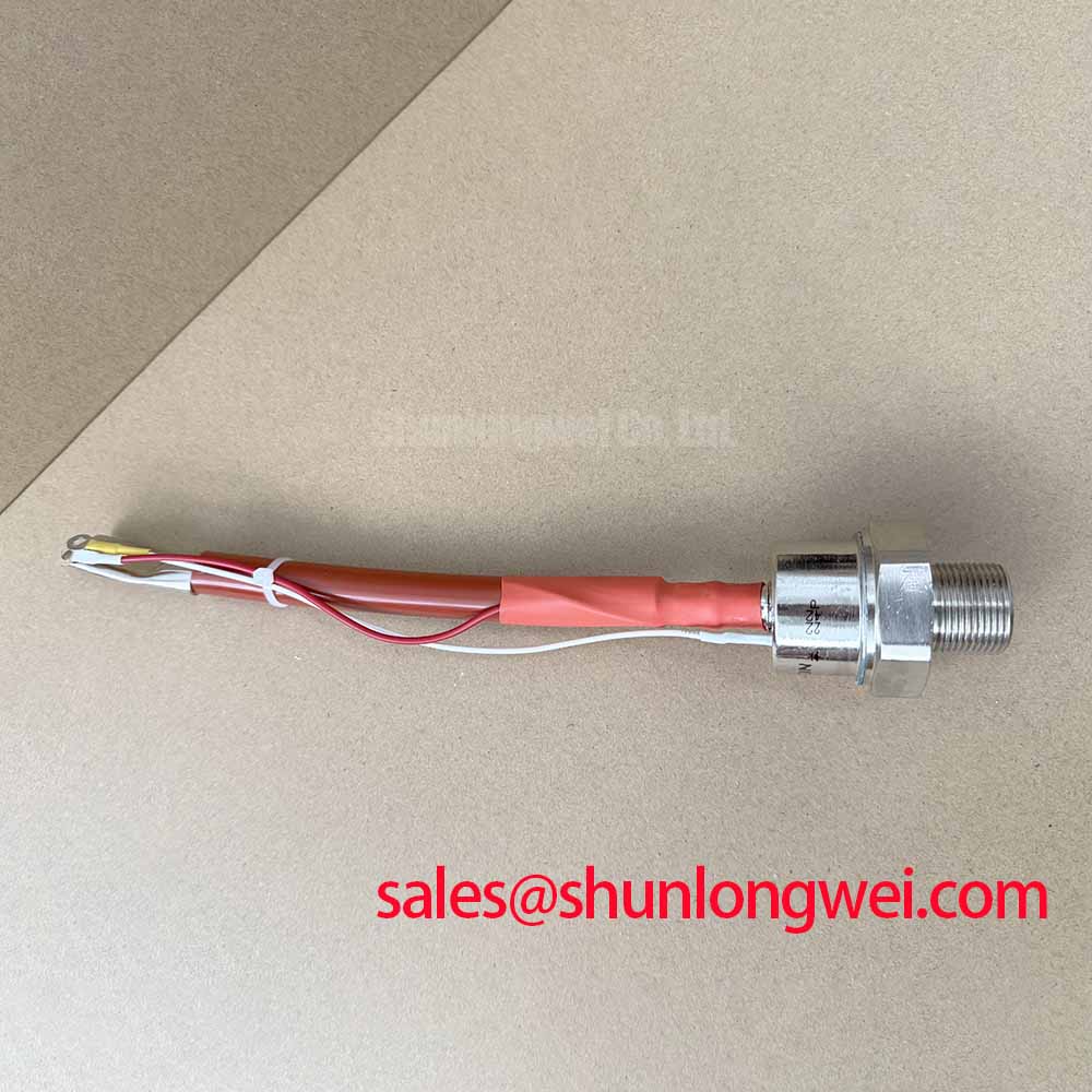
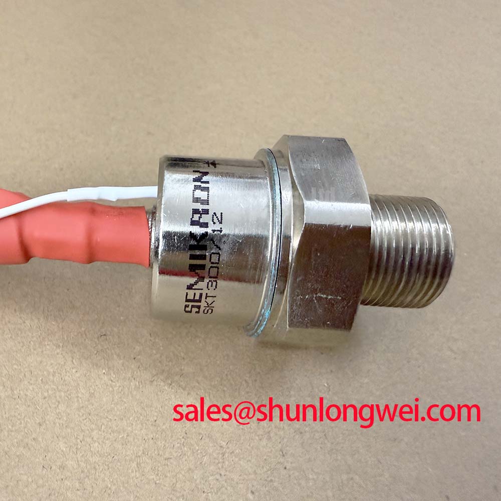
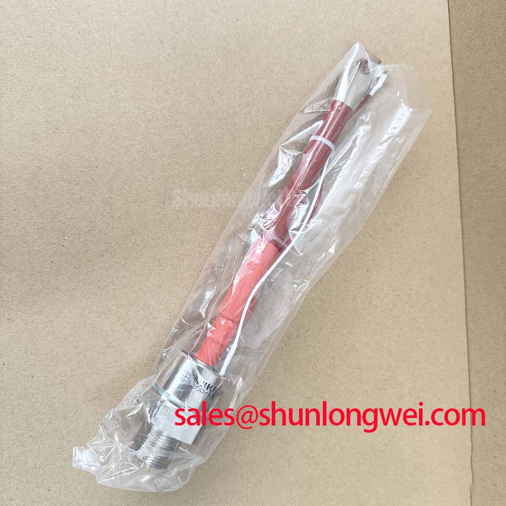
With the unit isolated from the power circuit, first verify the nameplate rating and inspect the terminal interfaces, mounting faces, and gate connections before reconnecting the SKT300/12 to a three phase soft starter assembly. The Semikron SKT300/12 thyristor module is officially rated for 1200V repetitive peak off state and reverse voltage, with an average on state current of 300A at case temperature 85°C. Its stated surge capability, gate trigger data, and thermal boundary should be checked against the original control and protection design rather than treated as a universal replacement rule.
| Official Datasheet Specification | Value |
|---|---|
| Repetitive peak off state and reverse voltage, Vdrm / Vrrm | 1200V |
| Average on state current, Itav, Tc 85°C | 300A |
| Surge on state current, Itsm, 10ms, 25°C | 5400A |
| Gate trigger voltage and current, Vgt / Igt | 3V / 150mA |
| Junction to case thermal resistance, Rth(j c), DSC | 0.09 K/W |
| Maximum junction temperature, Tvj max | 130°C |
The 5400A ITSM figure is an Official Datasheet Specification for a 10ms surge at 25°C; it is not a repetitive operating current rating. During soft starter commissioning, capture the current waveform at motor energization and after bypass contactor transfer. Compare the observed transient duty with the original protection coordination records, particularly where stalled rotor events, repeated starts, or upstream source disturbances are possible.
Before reapplying reverse voltage after a transient event, the system engineer should verify that the measured current has decayed as intended and that the thermal path can keep junction temperature below the official 130°C maximum. This is a Design Consideration because actual junction temperature depends on the heatsink, interface condition, duty cycle, airflow, and line waveform.
For a high voltage three phase motor solid state soft starter, evaluate phase current and gate firing consistency across the complete controlled assembly. An irregular phase current pattern can arise from control timing, gate wiring, supply imbalance, load conditions, or an associated protection path. Oscilloscope and current probe measurements against a known healthy signal path provide more useful evidence than assuming one isolated cause.
💡 Pro Tip: Keep the power bus arrangement compact and geometrically balanced to reduce inductive overshoot during current interruption, then verify voltage margin with measured switching waveforms.
Assembly Integrity & Layout Architecture: Implementing Semiconductor Protection Fuse Selection for SKT300/12
Fuse coordination should consider the module’s official 5400A surge current limit together with the semiconductor fuse manufacturer’s clearing and pre arcing I²t documentation. The available SKT300/12 parameters do not state a device I²t withstand value, so a valid numerical coordination result cannot be derived from the module data listed here alone. Engineers should use the original equipment protection study, fuse curves, prospective fault current, and tested assembly behavior to determine whether the clearing action protects the semiconductor under a short circuit fault.
Place the protection fuse in the intended current path with short, robust conductor routing. Terminal contact surfaces should be clean, flat, and tightened to the manufacturer specified hardware requirement. The module mounting clamp arrangement, bolt size, washer stack, and torque must also be confirmed from the applicable mechanical documentation; these details are not included in the stated official electrical ratings.
Thermal contact quality deserves the same attention as fault protection. The listed 0.09 K/W junction to case thermal resistance describes the module’s internal thermal path under its specified condition, not the complete case to heatsink path. A thin, uniform thermal interface material layer and an even mounting load are Design Considerations that help avoid localized temperature rise. For broader context on cooling-path decisions, see The Advanced Thermal Management Revolution.
Assembly Integrity & Layout Architecture: Implementing AC Input Transient Overvoltage Clamping for SKT300/12
The 1200V Vdrm / Vrrm rating defines the repetitive blocking voltage boundary of the SKT300/12. It does not establish that an AC input transient, cable reflection, or inductive interruption remains safely within that boundary. For long motor cable installations, reflected voltage waves and wiring inductance can alter the stress seen by the controlled power stage. Designers should measure the voltage at the relevant terminals under representative cable and motor conditions, then validate the selected clamping network against the measured peaks.
MOV and RC snubber networks are system level Design Considerations. Their selection depends on source voltage, surge exposure, wiring geometry, load behavior, energy capability, and the protection architecture of the complete starter. Use the applicable surge immunity requirements for the equipment rather than assigning a compliance claim to the module itself. Where gate timing or commutation overlap is investigated, the principle of dead time can help explain why control sequencing must be verified across the power circuit.
The gate trigger requirement is officially specified as 3V and 150mA. Verify that the existing gate drive delivers its intended pulse at the module connection under operating noise and current conditions. The trigger specification does not define a complete gate driver design, gate-cathode stress limits, or control board protection method. For related dielectric aging terminology, refer to time dependent dielectric breakdown.
Benchtop Waveform Tuning: Mitigating Stress via Phase Angle Voltage Profiling on SKT300/12
Phase angle profiling in a motor soft starter should be evaluated from measured line current, motor terminal voltage, heat rise, and acceleration behavior. A gradual firing angle progression can limit start current and mechanical torque shock, but the appropriate profile is determined by motor characteristics, driven load inertia, supply stiffness, and the installed bypass arrangement. It should not be set from the SKT300/12 current rating alone.
During commissioning, confirm that each phase receives the intended firing sequence and that the controlled current waveform returns to an acceptable operating condition after the start cycle. Harmonic current produced by phase controlled conduction should be assessed at the system level, especially where upstream transformers, generators, or sensitive control supplies are involved. The module itself must remain within its official 300A average on state current at Tc 85°C and 130°C maximum junction temperature limits.
Where a higher voltage or current class is being evaluated, engineers can compare the original electrical and mechanical requirements with the published data for the SKT340/18E. Such a comparison should include circuit topology, gate drive conditions, fuse coordination, mounting arrangement, thermal interface, and measured transient voltage, rather than relying on part numbering alone.