




Content last revised on October 20, 2026
MTDX320A1600V Operational Boundaries: Evaluating Uniform Heatsink Contact Pressure Limits
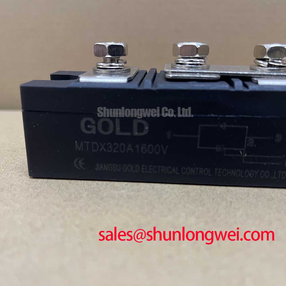
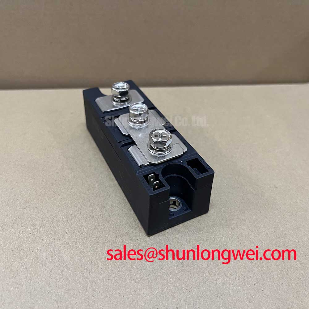
With the equipment isolated, I first inspect the copper baseplate, terminal hardware, and heatsink imprint before applying power. Uneven thermal compound transfer or a visible mounting distortion can prevent the specified Rth(j-c) of 0.080°C/W per arm from being achieved, even when the electrical readings appear normal.
The SanRex MTDX320A1600V carries an official repetitive peak off-state voltage of 1600 V VDRM and repetitive peak reverse voltage of 1600 V VRRM. Its official average on-state current is 320 A at Tc = 85°C, with an RMS on-state current of 502 A. For short-duration fault coordination, the listed surge current is 6000 A at 50 Hz, 10 ms. These values define the device rating boundary; actual furnace current remains dependent on cooling, conduction angle, busbar arrangement, and protection coordination.
| Parameter | Official Specification |
|---|---|
| Gate trigger voltage | 3 V maximum |
| Gate trigger current | 150 mA maximum |
| Maximum junction temperature | 125°C |
| Junction-to-case thermal resistance | 0.080°C/W per arm |
| Isolation voltage | 3600 V RMS at 50 Hz |
| Mounting torque | 5 ± 1 N·m |
Clean both mating surfaces and spread thermal compound as a continuous, thin film rather than using a thick cushion. Tighten the mounting hardware progressively so the baseplate seats evenly. The official mounting torque is 5 ± 1 N·m; the fastener type, washer arrangement, and heatsink construction must remain compatible with the equipment assembly.
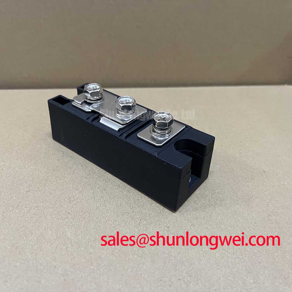
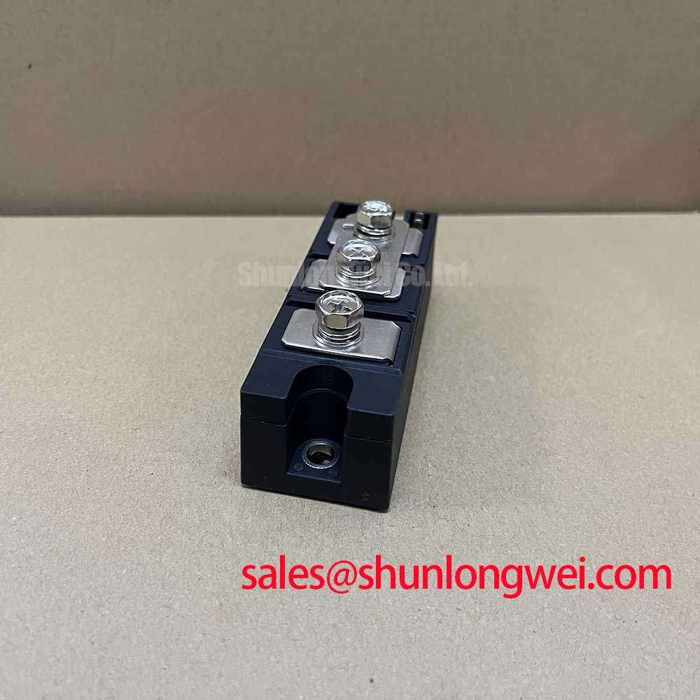
For a replacement in a medium-frequency induction melting or hardening furnace, compare the original terminal layout, gate circuit routing, cooling path, and fuse coordination before energizing. The PK90FG160 may be reviewed as a separate same-family reference, but it should not be treated as an automatic substitute without checking electrical and mechanical compatibility.
⚠️ Field Alert: Do not loosen or insert power terminals while the DC link or AC supply remains energized, and verify the specified 5 ± 1 N·m mounting torque during reassembly.
Transient Dynamics & Electrical Design: AC Line Surge Immunity and Lightning Transients
AC input protection for this module should be assessed around the complete power path, including line impedance, upstream fuses, MOV energy capability, RC snubber placement, and the physical distance to the thyristor junctions. The 1600 V repetitive blocking rating is an official device limit, not a system-level permission to expose the module directly to lightning or switching surges.
For IEEE 61000-4-5 test conditions, designers should select the surge protection network from the actual source impedance and expected surge waveform. An MOV is normally evaluated by clamping behavior, repetitive energy, and failure mode under the intended line arrangement. The selected clamping level must protect the semiconductor while remaining compatible with the AC operating voltage. An RC snubber can reduce fast voltage transitions across the thyristor, but its location and damping behavior should be verified on the assembled circuit rather than copied from a different converter.
Long motor or coil cables can behave as transmission lines. Reflections may produce a terminal voltage approaching twice the incident step in an unfavorable installation, so cable length, termination, stray capacitance, and measurement probe placement deserve attention during commissioning. The practical objective is to control peak voltage at the module terminals and confirm it against the specified voltage rating during switching tests.
Parallel positive-temperature-coefficient devices can develop useful static current sharing, but dynamic sharing is affected by gate timing, loop inductance, thermal coupling, and busbar symmetry. Keep the current paths geometrically consistent and verify each branch under the intended firing sequence. Laminated busbars can reduce commutation loop inductance; the resulting turn-off overshoot still requires oscilloscope verification at the module terminals. General capacitive coupling and gate transient behavior can be reviewed through the discussion of the Miller effect.
In a furnace power cabinet, the upstream rectifier and firing supply should be reviewed as one topology. The MTC160-12 provides a related reference point for examining the preceding power stage, while the final protection values remain determined by the complete converter design.
Field Diagnostics & Commissioning: I2t Sub-Cycle Melting Rating in MTDX320A1600V Topologies
When a dead-short event is suspected, isolate the module, record the fuse condition, and compare the installed semiconductor fuse with the equipment’s approved I2t coordination data. The module’s 6000 A surge current rating at 50 Hz and 10 ms describes a specified surge condition; it does not replace the fuse manufacturer’s clearing-energy data or the converter protection study.
Check each main terminal for heat discoloration, looseness, and evidence of localized arcing. Then perform cold-state resistance and diode or thyristor junction checks using a known-good reference and the correct test polarity. A low or inconsistent reading should be correlated with gate wiring, parallel arms, fuse operation, and the surrounding commutation network rather than assigned to one cause without circuit context.
Fuse selection should compare the fuse clearing I2t against the semiconductor withstand requirement for the actual fault duration and prospective current. Use the approved coordination table for the equipment topology, then validate the result with controlled commissioning tests. The Power Semiconductor Selection Guide offers a broader framework for checking voltage, current, thermal, and protection boundaries.
During gate commissioning, the official limits are 3 V maximum VGT and 150 mA maximum IGT. Confirm the pulse reaches the correct terminals with the intended polarity and that wiring inductance does not distort the command at the module. Gate insulation and dielectric stress are system concerns; the general discussion of quantum tunneling is background semiconductor theory, not a device-specific qualification claim.
After replacing the unit, bring the furnace power stage up under controlled load while monitoring terminal voltage, current balance, heatsink temperature, and fuse behavior. Stop the test if the thermal rise, commutation waveform, or branch current departs from the established equipment baseline.