





Content last revised on September 10, 2026
Shielded FFC/FPC Flat Flexible Cable Grounding across 360-Degree Connector Shells
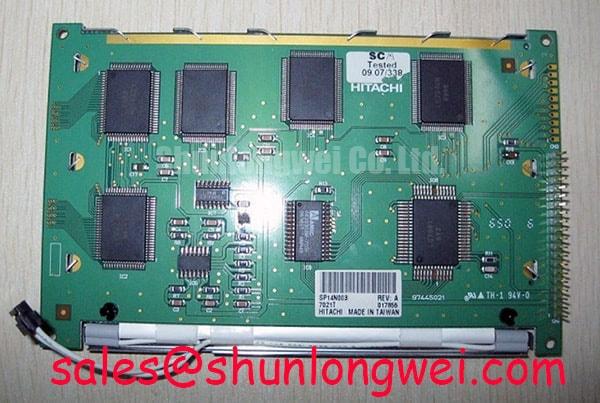
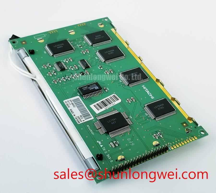
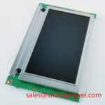
For a vehicle-mounted HMI, the first practical compatibility check is the cable path between the display and its controller. Record the installed FFC or FPC contact orientation, connector position, cable bend direction, and shield termination method. The SP14N003 factory information supplied for this product page does not specify an LVDS pinout, TTL mapping, connector pitch, cable length, or differential impedance. The system integrator should therefore verify each item from the original panel drawing or the equipment service documentation rather than assuming compatibility from the model number alone.
Where the display cable passes close to a variable-frequency motor drive, traction inverter, or switching power stage, a continuous shield termination can help reduce the area exposed to common-mode noise. This is a Design Consideration, not an SP14N003 factory performance guarantee. A 360-degree connector-shell bond may be evaluated when the mechanical connector system supports it, while ferrite suppression should be selected only after checking the cable’s common-mode current, signal bandwidth, and display timing margin.
Pixel jitter, intermittent horizontal bands, or unstable image data should be investigated across the complete signal path. Compare the suspected panel with a known-good controller, inspect the reference clock and data lines with suitable probing, and check whether noise changes with motor switching activity. TTL and LVDS systems have different signaling arrangements, so the engineer should verify transmitter format, clock polarity, data hold behavior, and receiver requirements from the source documentation. Fourier-series analysis can help separate periodic inverter-related components from random signal disturbances; the underlying harmonic-analysis method is described in this Fourier Series reference.
Dual-Channel CCFL High-Voltage Resonant Inverter Striking Voltage & Ignition Debugging
The supplied factory data classifies SP14N003 as a TFT-LCD display module but does not confirm a CCFL backlight, dual-channel inverter arrangement, LED backlight, striking voltage, lamp current, PWM input, optical contrast ratio, sunlight readability, or half-life rating. The system integrator should verify the required backlight technology from the original panel documentation. Do not connect a replacement inverter or LED driver until the backlight connector, polarity, enable signal, dimming method, and protection behavior have been identified.
For legacy equipment that uses a high-voltage CCFL inverter, cold-start behavior should be checked with an appropriate high-voltage probe and an isolated test arrangement. Observe the ignition sequence, current regulation, acoustic noise, and shutdown response while keeping the panel’s original wiring arrangement under review. A failed start can involve the lamp, inverter transformer, wiring insulation, connector contact, control signal, or protection circuit, so a single symptom should not be assigned to one cause without measurement.
For an LED-based assembly, inspect the constant-current driver and confirm whether brightness control is analog, PWM, or a system-specific digital command. A stated dimming ratio or optical performance value must come from the exact panel or driver datasheet; it cannot be inferred from the SP14N003 product category. Direct sunlight evaluation should be performed with the completed cover glass, bezel, viewing angle, and ambient-light environment because these mechanical and optical elements influence usable contrast.
The product record for SP14N003 should be used as the sourcing reference, while the original equipment documentation remains the controlling source for electrical backlight integration.
Thermal Expansion Clearance Sizing across Heavy Industrial Metal Enclosure Cutouts
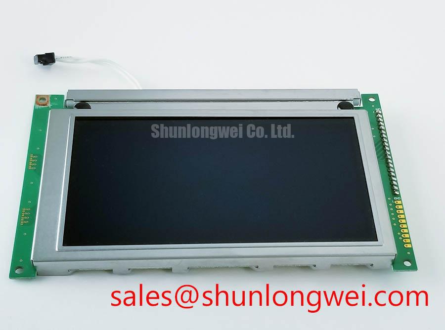
Before installation, measure the existing opening, visible bezel envelope, mounting-hole pattern, display depth, connector clearance, and cable exit direction. The official factory information supplied here confirms the product category and TFT-LCD module construction, but it does not provide the panel outline, active-area dimensions, mounting-hole coordinates, M3 fastener limits, bezel tolerances, or recommended tightening torque. These values must be taken from the applicable mechanical drawing rather than estimated from the product name.
When a metal enclosure is used on an AGV or forklift telematics display, the mounting design should support the panel without twisting the bezel or transferring concentrated force into the glass assembly. This is a Design Consideration. The enclosure engineer should allow the panel to sit naturally within the opening, check gasket compression independently, and verify that the display does not contact the chassis during vibration or thermal cycling. Any fastener torque must follow the panel drawing or the equipment manufacturer’s assembly specification.
Cold environments can alter liquid-crystal response behavior and may increase visible motion smear or slow image transitions. The supplied SP14N003 data does not state an operating-temperature range, GTG response time, heater requirement, or low-temperature optical specification. If the display is evaluated for an outdoor warehouse vehicle, the integrator should test startup, image refresh, contrast, condensation exposure, and enclosure heat distribution at the actual operating extremes. A heater strip, if present in the equipment, should be controlled by the system designer after thermal measurements rather than treated as an inherent feature of this display module.
For a same-size or similar-resolution replacement study, engineers may also compare the mechanical drawing and interface documentation for TX23D11VM2BAA. That comparison is a neutral sourcing reference; physical fit, timing, connector orientation, and backlight compatibility still require verification.
TTL 24-Bit Digital RGB Bus Synchronization & Logic Power Rail Verification
The SP14N003 information provided for this page does not confirm a 24-bit TTL RGB interface, LVDS interface, logic-supply voltage, power-on timing, JEIDA or VESA mapping, pixel clock range, or differential routing requirement. The system integrator should verify the required supply voltage from the original panel documentation. Applying an assumed rail or pin assignment can damage the module or produce misleading symptoms during a replacement test.
Start with connector identification and continuity checks performed with power removed. Map the controller output to the original panel documentation, including data-bit order, clock, control signals, enable lines, ground returns, and backlight signals. If the source uses LVDS, confirm lane order, polarity, serialization format, and receiver timing. If it uses TTL RGB, confirm whether the controller’s color-bit arrangement follows JEIDA, VESA, or another documented convention. A split image, incorrect colors, unstable synchronization, or a blank screen may indicate a mapping, timing, power, or cable problem; verify the signal path with an oscilloscope and a known-good reference rather than assigning a single cause.
Power sequencing should be checked at the panel connector while monitoring the logic rail, reset or enable behavior, display data activity, and backlight activation. The correct rise-time window and delay relationships are system-dependent unless explicitly stated in the panel datasheet. Designers should also minimize parasitic coupling between high-current traction wiring and display signal returns, then validate image stability during motor start, braking, charging, and communication activity.
For broader installation guidance covering industrial TFT-LCD selection, interface checks, and practical evaluation methods, consult The Ultimate Guide to Industrial TFT LCD Technology. 💡 Pro Tip: Keep the display clock and associated data routing consistently referenced to the intended return path, then verify jitter and image stability at the completed harness rather than only on the bench.



