

Content last revised on October 14, 2026
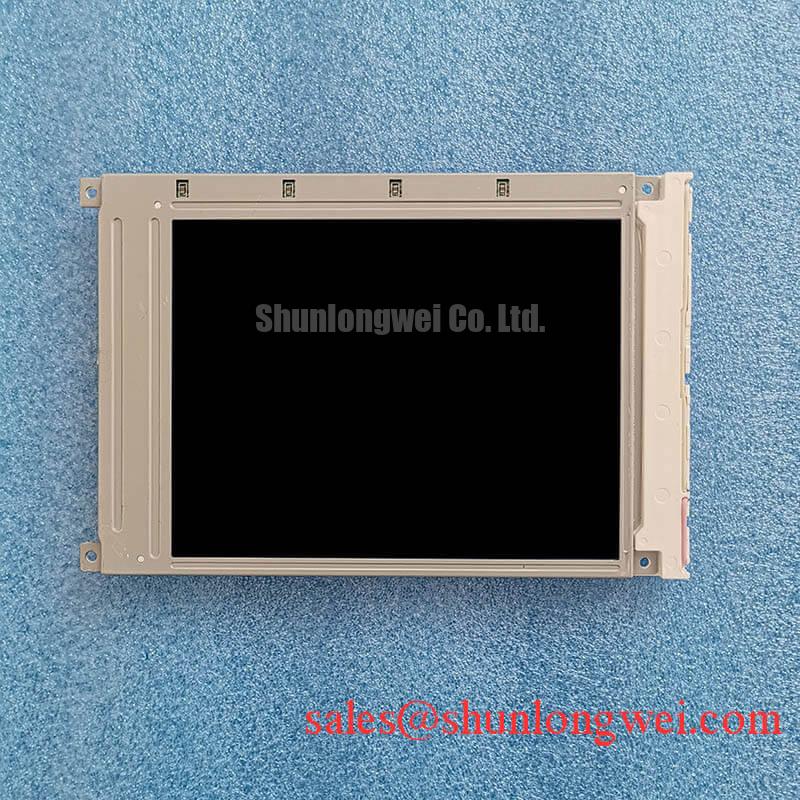
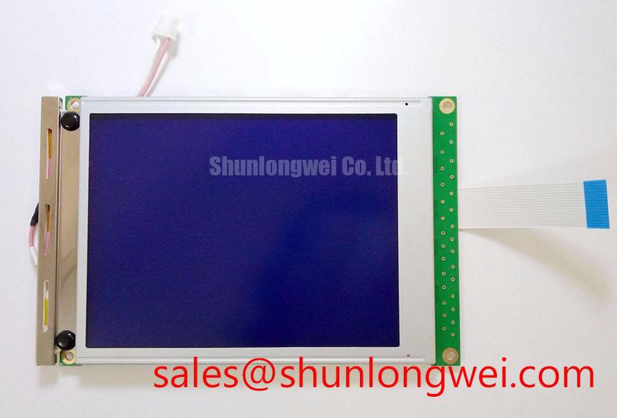
SP14Q009 KOE / Hitachi FSTN/STN Monochrome Industrial LCD Panel
Check the panel connector, frame timing, and power rail sequence before applying power to a service unit. The SP14Q009 is identified as a KOE / Hitachi industrial LCD panel with a monochrome passive-matrix construction. These attributes make interface verification more important than applying assumptions from an unrelated TFT replacement.
For a repair engineer, the first practical task is to document the installed controller configuration, including the display supply arrangement, contrast rail, frame timing, line pulse, and dot clock. The product identification alone does not establish the signal levels, timing requirements, or backlight interface, so the original panel documentation and host schematic should govern the replacement decision. This is especially relevant in surgical navigation displays, ultrasound consoles, CNC operator panels, and other equipment where a visually similar panel can still have incompatible timing or mechanical interfaces.
Parallel Digital Signal Reflections Mitigation via Series Damping Termination Resistors
Parallel display buses require attention to CP, LP, and FLM timing because reflections can alter the sampling point even when the logic supply appears stable. A service oscilloscope check should compare the clock and synchronization waveforms at the controller output and at the panel connector. Look for ringing, excessive edge distortion, unstable duty cycle, or timing movement during contrast and refresh changes.
Design Consideration: Series damping can be evaluated when the interconnect behaves as a transmission line and the observed reflection returns during the receiver sampling window. The resistor location, value, and package parasitics are system-dependent; the correct setting should be selected from measured waveform behavior rather than assigned as a universal value for SP14Q009. Keep the clock, line pulse, and frame pulse routing compact, with a controlled return path and consistent reference plane.
Power sequencing deserves equal attention. The host should establish the logic supply, contrast or bias rail, and display timing in the sequence defined by the panel and controller documentation. Applying a bias rail out of sequence can create unwanted electrical conditions and may contribute to abnormal display behavior. When a legacy controller is being repaired, record the rise and fall order of each rail instead of relying only on a static voltage measurement.
💡 Pro Tip: Match the parallel clock routing environment to the original controller layout and verify signal integrity at the panel connector, not only at the source device.
Although DisplayPort and HDMI use high-speed architectures rather than a direct passive-matrix bus, their protocol behavior is useful when tracing a modern converter board that feeds a legacy display subsystem. Reference material on the DisplayPort High Bit Rate packetized protocol and HDMI protocol can help separate converter-side faults from panel-side timing faults.
High-Ambient Readability and Optical Condition
In direct sunlight, readability depends on the panel's optical mode, polarizer condition, viewing angle, and front-surface glare. Reflective and transflective assemblies may use ambient illumination, while transmissive assemblies rely on a backlight; monochrome FSTN or STN construction alone does not establish readability without active illumination. Inspect the viewing window for haze, localized bubbling, yellowing, delamination, and uneven optical density. A panel that appears acceptable under bench lighting may show severe contrast loss when installed behind a protective cover or exposed to a bright operating environment.
Legacy transflective assemblies can experience polarizer and adhesive aging under ultraviolet exposure and elevated enclosure temperature. These changes may appear as washed characters, uneven background tone, or a milky region that moves with viewing angle. The practical evaluation is to compare the candidate panel under the actual cover glass, bezel, and ambient illumination geometry. Anti-glare or anti-reflection treatment belongs to the complete display stack; it should not be assumed from the SP14Q009 product identification.
Where an older terminal uses a fluorescent inverter, the high-voltage ignition waveform, ballast behavior, creepage path, and transformer insulation must be assessed as part of the system. Do not apply a legacy inverter to an unverified panel interface. Where the host has been converted to LED illumination, the constant-current driver, dimming method, open-load response, and short-circuit protection should be checked independently. A stated backlight lifetime, PWM range, or flicker performance cannot be assigned to this passive LCD panel without the matching backlight assembly and its source documentation.
| Evaluation point | SP14Q009 | TX26D211VM0BAB |
|---|---|---|
| Manufacturer reference | KOE / Hitachi | Confirm from the applicable product documentation |
| Panel category | Industrial LCD panel | Confirm from the applicable product documentation |
| Display technology | Monochrome passive matrix | Confirm before any compatibility assessment |
| Mechanical fit | Verify the documented outline and mounting details | Compare outline, connector, and mounting geometry |
| Replacement decision | Match against the installed host interface | No replacement relationship established here |
The table separates product identity from compatibility evaluation; it does not establish the linked panel as a replacement. A similar appearance is not enough: connector pitch, viewing area, cable exit, contrast bias, frame timing, and enclosure aperture all affect field compatibility.
HV Lead Wire Creepage Insulation & Secondary Transformer Corona Discharge Screening
Where the installed system uses a fluorescent backlight, high-voltage lead inspection should begin at the inverter output, cable termination, tube interface, and nearby grounded metalwork. Carbon tracking, pinched insulation, darkened solder joints, and intermittent brightness changes can indicate corona or arcing in the installed lighting circuit. The safe working method is to isolate power, discharge the inverter according to its service procedure, and inspect the complete creepage path before reconnecting the panel.
Design Consideration: Ignition voltage, sustained lamp voltage, tube current, creepage distance, and transformer corona behavior belong to the selected backlight and inverter combination, not to the basic SP14Q009 identity supplied here. These values must be matched to the original lighting architecture. A replacement inverter should also be assessed for open-lamp detection and current regulation, since an incorrect response can produce repeated restart pulses or uneven illumination.
The negative display rail, commonly associated with contrast control in legacy monochrome assemblies, should be checked for ripple under active scanning. Ripple filtering, grounding, and any temperature-compensation circuitry influence character contrast and grayscale stability. If the image changes as the enclosure warms, compare the contrast rail and panel temperature together while watching for drift in the host bias circuit.
For broader display comparison, the TX18D216VM0BAA may be reviewed against its own documentation. It should not be treated as an automatic electrical substitute for SP14Q009.
Diagnosing Missing Horizontal Display Rows / Vertical Columns and Interconnect Faults
Missing rows or columns should prompt an interconnect and alignment inspection before pressure is applied to the bezel. Inspect the flex termination, any elastomeric connector or zebra strip, contact surfaces, and frame alignment under magnification. Oxidation, adhesive creep, vibration displacement, or uneven compression can interrupt selected electrodes while leaving the remainder of the image functional. Bonded flex delamination or an internal driver fault may require specialist repair or panel replacement rather than mechanical adjustment.
Where the assembly uses a serviceable compression contact, mechanical correction should preserve even contact across the active width. Excessive local pressure can distort the glass or shift the conductive interface, while insufficient pressure can leave intermittent lines that return when the enclosure is flexed. If the bezel has been removed, restore its seating geometry and check that the cable exits without a sharp bend or tensile load.
After mechanical service, review CP, LP, and FLM at the panel connector. A missing row or column accompanied by unstable timing may involve the controller path rather than the glass interface. The supply and display enable sequences should follow the panel and controller documentation. A controlled comparison between a known-good signal path and the repaired assembly is more useful than assigning a single fault to the panel.
For broader service reference on display architecture, timing, and selection principles, consult The Ultimate Guide to Industrial TFT LCD Technology.