Content last revised on October 13, 2026
G057AGE-T01 Display Identification and Replacement Checks
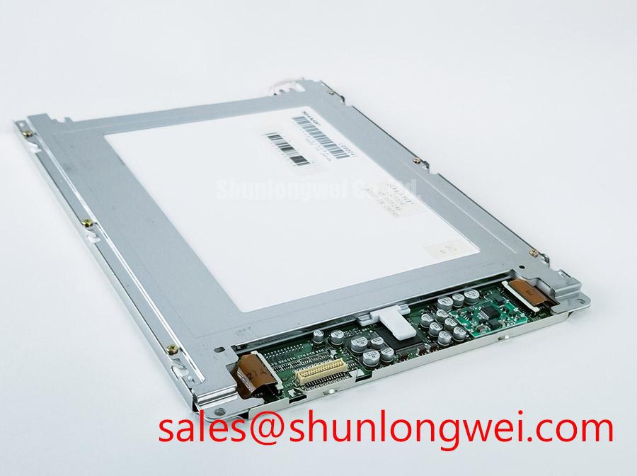
When a railway display goes dark, first isolate the panel from its host controller, inspect the display connector for incomplete engagement, and verify that the replacement’s mechanical outline matches the removed unit before applying power. The G057AGE-T01 is an AUO TFT-LCD active matrix color display module for industrial LCD and HMI applications. The original panel documentation remains the controlling reference for supply voltage, interface assignment, timing, backlight drive, and mounting dimensions.
For a railway passenger information system or cab signalling display, treat the panel as one part of a complete optical, electrical, and mechanical assembly. The system integrator should verify the required supply voltage from the original panel documentation, then compare connector keying, pin assignment, display timing, backlight control, and bezel clearance before installation. A visually similar panel can still produce a white screen, unstable image, incorrect orientation, or backlight protection shutdown when its host electronics expect a different interface.
Radiated Emissions Compliance and Backplate Grounding Considerations
Pixel jitter and horizontal noise bands near a variable frequency motor drive should be investigated through the complete display cable path rather than attributed to the LCD cell alone. The display cable route, controller ground, metal backplate, chassis bonding points, and nearby power switching hardware can form paths for high frequency interference. A practical design consideration is to provide a low impedance, continuous shield termination around the cable entry where the enclosure and cable construction support it, while avoiding long pigtail connections that can increase common mode coupling.
Backplate grounding should follow the enclosure’s approved earthing architecture. Multi-point bonding may reduce high frequency voltage differences across the display frame, but the final arrangement is system dependent because DC safety grounding, protective earth, signal reference, and EMC bonding do not always serve the same purpose. During troubleshooting, compare the image with the motor drive disabled and then operating under representative load. If the disturbance follows drive switching activity, use an oscilloscope or suitable EMC measurement method to compare the reference potential at the controller, cable shield, and display frame.
Common-mode ferrite suppression can be evaluated as an engineering recommendation when cable-borne noise remains after routing and bonding have been corrected. The ferrite’s impedance profile must match the disturbance spectrum and the signalling requirements; an unsuitable part can affect signal integrity or create a new resonance. Do not claim CISPR Class A or Class B compliance from the display module alone. EMC performance belongs to the assembled equipment, including enclosure, cable layout, grounding, drive electronics, and software operating state.
Ambient light also changes the field diagnosis. Reflections can make a stable image appear washed out, while a true timing or grounding fault may show as moving bands or intermittent pixel displacement. The LCD polarizer and optical glass principles are useful when separating optical contrast loss from electronic noise. Contrast ratio, anti-glare behavior, viewing angle, and sunlight readability should be checked against the original equipment acceptance requirement rather than assumed from the G057AGE-T01 model designation.
High-Humidity Storage Margins and Delamination Prevention
Humidity-related display faults often become visible at the bezel edge, connector entry, or optical surface before the image fails completely. Storage and operating exposure at elevated humidity should therefore be handled as a system environmental design consideration, not as an automatic rating of the G057AGE-T01. Inspect for haze, edge lifting, trapped moisture, corrosion at exposed contacts, and changes that appear after the display returns to room conditions.
Sub-zero operation can increase liquid-crystal response lag and make moving text or grey transitions appear slower. This is a physical behavior of LCD systems and should be evaluated with the actual controller timing, image content, and enclosure temperature, within the panel’s specified operating limits. A railway cab display that appears normal during a warm bench test may show visible transition lag after a cold soak. If the equipment includes a heater or controlled enclosure, its use must be determined by the host design and validated against the panel’s approved environmental documentation.
Perimeter sealing, optical bonding, and enclosure drainage should be assessed together. Optical bonding can reduce an air gap and limit the path for condensation, but it must not be claimed as an integrated feature of this model without supporting manufacturer documentation. If the panel is being fitted into a sealed HMI bezel, confirm that compression, adhesive selection, service access, and thermal expansion are compatible with the display assembly. Excessive local pressure can create bright spots, dark areas, or nonuniformity that may be mistaken for liquid-crystal damage.
For high-humidity storage evaluation, record the panel condition before exposure, after controlled conditioning, and after electrical operation resumes. Pay particular attention to image uniformity, backlight stability, connector contact quality, and any edge discoloration. The Tianma industrial TFT-LCD technology reference provides useful industry context for comparing environmental and optical requirements across industrial display families, but it does not define AUO model-specific ratings.
Suppressing Acoustic Buzz and EMI Across PWM Backlight Operation
Backlight troubleshooting should begin by identifying the installed driver topology from the original equipment documentation. A CCFL inverter and a constant-current LED driver are different electrical systems, and their ignition, dimming, feedback, and protection behavior cannot be interchanged by matching only the panel size. The model designation alone should not be used to infer backlight technology, ignition voltage, PWM range, dimming ratio, or acoustic performance specifications; consult the G057AGE-T01 documentation.
Audible buzz can originate in the driver, transformer, inductor, ceramic capacitor, mounting surface, or enclosure resonance. To localize it, compare the sound with brightness control disabled, then across the equipment’s normal dimming range while monitoring backlight current and the control signal. If the noise changes with PWM duty or frequency, inspect the driver’s switching behavior and mechanical coupling. A common design consideration is to keep the backlight control return path separate from noisy power switching returns until the approved interface reference point, while validating image stability at the chosen operating condition.
PWM frequency and duty-cycle linearity should be selected by the system designer according to the driver, camera exposure requirements, human flicker sensitivity, and display response. A nominal frequency range cannot be treated as an official characteristic of this panel without supporting documentation. When a railway passenger information display is recorded by service cameras, test the complete display at several brightness levels because banding can result from interaction between PWM, camera shutter timing, and the controller’s frame timing.
Do not transfer high-voltage CCFL assumptions to an LED assembly, or LED-driver assumptions to a CCFL inverter. The required replacement procedure is to identify the original backlight interface, confirm the controller’s enable and dimming signals, and validate startup and shutdown behavior with the panel connected. ⚠️ Field Alert: disconnect equipment power and allow the host supply to discharge before inserting or removing the display cable.
Industrial Bezel Envelope and Mounting Stress Control
Mechanical fit should be checked before electrical commissioning. Measure the available bezel opening, mounting-hole pattern, connector clearance, cable bend path, and rear enclosure depth against the removed display assembly. The G057AGE-T01 model designation does not replace a dimensional drawing for a drop-in mechanical substitution.
Fastener loading must remain even across the frame. A cross-pattern installation is a reasonable design consideration when the mounting structure uses multiple screws, because it can reduce uneven pressure during seating. The correct torque is determined by the screw size, thread material, bracket construction, gasket compression, and manufacturer’s mechanical specification; it should not be presented as a G057AGE-T01 factory parameter without documented support. Tightening one corner fully before the other mounting points can distort the bezel or introduce local optical nonuniformity.
After installation, examine a dark test image and a light grey field at several viewing angles. Localized shadows, bright corners, or pressure marks can indicate mechanical loading, enclosure warp, contamination, or cable interference. The diagnostic result should be compared with the panel before final bezel closure, because later access may require removing the entire HMI assembly. Avoid routing the display cable across sharp edges or directly beside high-current switching conductors; maintain the system’s approved bend radius and strain relief arrangement.
Long-term static content also requires a system-level display policy. Fixed logos, status bars, and railway route information can remain in the same area for extended periods, so designers should consider pixel shifting, periodic content refresh, suitable brightness control, and an approved screen saver where the controller supports them. These measures are design considerations and do not constitute a guaranteed burn-in or image-retention rating for the panel.
For cross-reference work, engineers evaluating another display with similar size or resolution can review LQ057Q3DC03 as a separate product record, then compare interface, dimensions, optical behavior, and backlight requirements without assuming interchangeability. Broader enclosure, bonding, grounding, and environmental planning is covered in Industrial Display & HMI Solutions.