


Content last revised on September 25, 2026
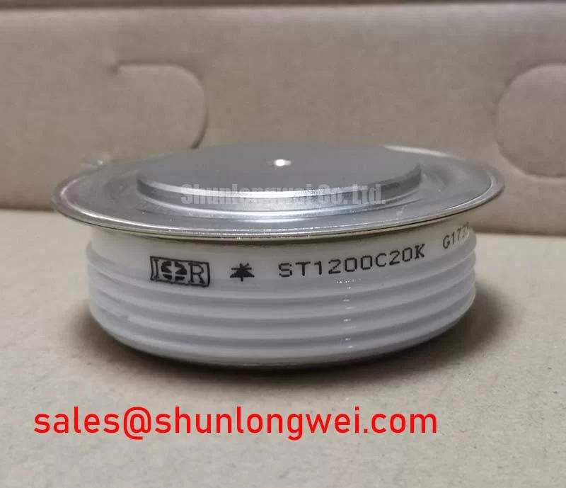
ST1200C20K Circuit Protection & Reliability: Calibrating Type 2 Coordination for Sub Cycle Dead Short Events
For a high current green hydrogen electrolyzer DC power rectifier, protection coordination should begin with the semiconductor fuse documentation and the rectifier’s verified fault path. The 1200.0 A current classification identifies the scale of the device, but it does not by itself establish a suitable fuse, clearing time, or short circuit withstand capability. Designers should compare the selected fuse clearing energy and published I2t data with the ST1200C20K thyristor and diode withstand limits stated in the relevant technical documentation.
The practical check is to document the fuse class, pre arcing I2t, total clearing I2t, prospective fault current, and the actual conductor impedance between the DC bus and module terminals. If any of these values are unavailable, the coordination result should remain an engineering assumption rather than a verified protection claim. Terminal interfaces should be inspected for clean contact surfaces, correct conductor preparation, and even clamping force. The equipment designer should also confirm whether the circuit requires line side protection, DC output protection, or both.
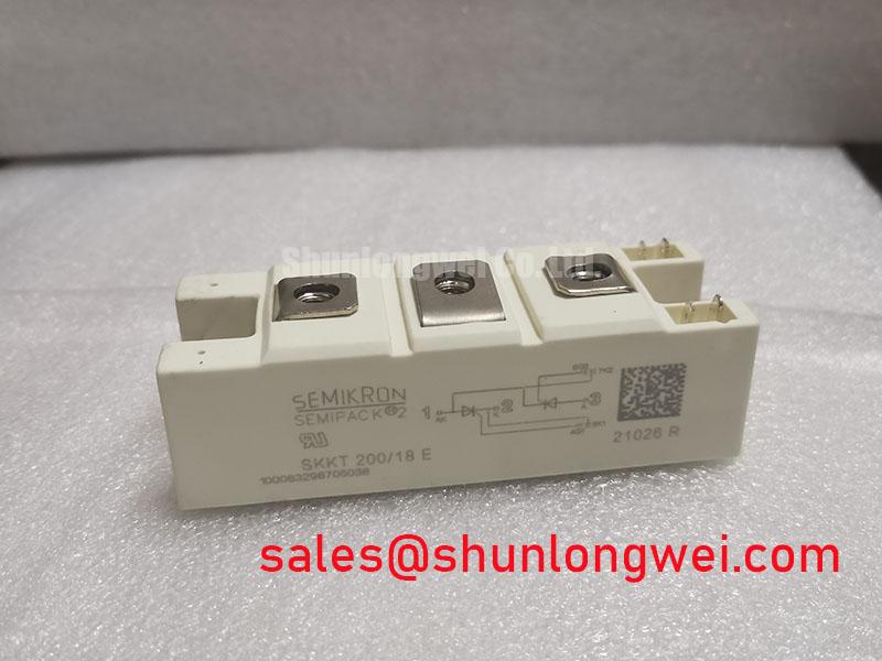
For neutral cross reference work, engineers evaluating a different high current bridge assembly may review SKKT500/14E as a separate product record. It should not be treated as an automatic substitute because voltage class, circuit topology, thermal interface, gate characteristics, terminal arrangement, and protection coordination must match the original application.
Safety Interlock Note: Isolate and verify the DC link is fully discharged before disconnecting terminals or performing cold resistance checks.
ST1200C20K Operational Boundaries: Evaluating Turn On Current Rise Limiting
Turn on behavior in a controlled rectifier depends on the firing circuit, supply impedance, commutation conditions, load profile, and stray inductance. A datasheet confirmed gate trigger voltage, gate trigger current, latching current, holding current, critical rate of rise of off state voltage, and critical rate of rise of on state current should be checked before the ST1200C20K is integrated into a firing controller. These values are not included in the supplied listing data and should not be inferred from the 1200.0 A current classification.
RC snubber selection is a system engineering task. The designer should evaluate the device’s documented dv/dt sensitivity, the actual recovery behavior of the complementary diode path, and the measured switching waveform at the module terminals. A series reactor or other current rise limiting method may be considered when the load and transformer leakage do not provide sufficient natural limitation. The final component values must be established through oscilloscope testing, thermal verification, and fault protection review rather than copied from an unrelated rectifier design.
In a high current electrolyzer supply, a suitable test plan should record firing angle, line current, DC output ripple, commutation overlap, terminal voltage, and temperature at the baseplate interface. Unexpected current sharing or irregular firing may also involve the controller, pulse transformer, wiring symmetry, or supply distortion. The diagnostic process should therefore compare all phases and gate channels against a known good reference instead of assigning a single cause from one waveform.
ST1200C20K Circuit Protection & Reliability: Calibrating Baseplate Thermal Resistance
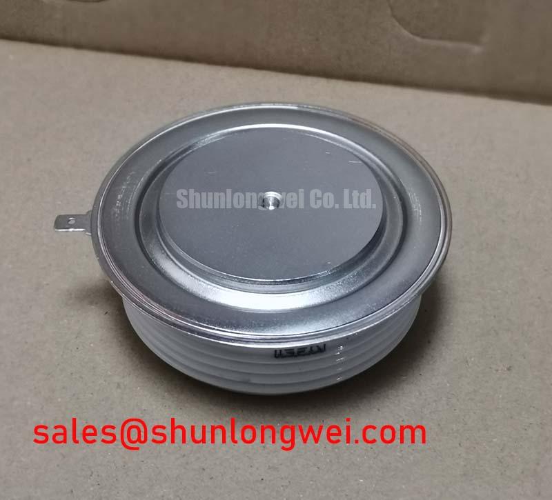
The Power Block / Bridge Case requires a mechanically stable thermal path to the heatsink. The available product data confirms the package family but does not provide a numeric junction to case thermal resistance, case dimensions, mounting torque, or thermal compound thickness. Those parameters must be taken from the applicable Vishay documentation or the equipment assembly drawing before production installation.
During service replacement, inspect the heatsink for flatness, contamination, burrs, and evidence of uneven pressure. The thermal interface should cover the intended contact area without creating air pockets or forcing the module to bend during tightening. Mounting hardware should be tightened according to the manufacturer’s specified sequence and torque. If no model specific torque is available, the installer should obtain it from the original assembly documentation rather than apply a generic value as an official ST1200C20K limit.
Thermal validation should use the actual current waveform and duty cycle of the rectifier. Measure the case or baseplate temperature at a repeatable location, confirm airflow or liquid cooling conditions, and compare phase temperatures under balanced operating conditions. A temperature difference between positions may indicate contact pressure variation, busbar imbalance, measurement placement error, or unequal electrical loading. The result should be reviewed against the device’s official junction temperature and power dissipation limits once those values are confirmed.
Long duration reliability claims require a defined test method and source data. The product record alone does not establish FIT rate, operating life, cosmic ray robustness, single event burnout performance, altitude derating, insulation life, or EMC certification. The technical discussion of industrial drive efficiency in Unlocking Efficiency in Industrial Drives may provide broader system context, but it does not replace the ST1200C20K device documentation.
ST1200C20K Operational Boundaries: Evaluating High di/dt Gate Firing and Pulse Train Timing
The ST1200C20K is identified as a thyristor/diode module, so gate firing analysis must follow thyristor trigger requirements rather than IGBT gate drive assumptions. The firing circuit should be checked for pulse amplitude, pulse current, pulse width, repetition behavior, isolation, return path, and synchronization with the line voltage. The supplied product data does not confirm a gate current rise rate, back porch holding current, or multi pulse timing limit; these values must be verified from the applicable device datasheet.
A practical bench test should monitor the gate to cathode waveform together with anode to cathode voltage and load current. The measurement arrangement needs suitable isolation and bandwidth, with probe placement that does not introduce an unintended return path. If the controller uses pulse trains, verify that every pulse reaches the intended gate terminal under the worst expected temperature and supply conditions. Irregular triggering may be associated with isolation components, wiring inductance, control timing, noise coupling, or insufficient gate drive, so each part of the firing chain should be checked.
Gate circuit protection should be coordinated with the module’s published trigger limits and the firing transformer or driver output capability. Minimize the physical loop area between the firing source and gate return to reduce noise pickup, then validate commutation and turn off behavior at the actual power circuit. High current busbar symmetry also deserves attention because unequal parasitic paths can produce different phase waveforms and complicate thermal sharing. Engineers may consult Interface State Density and Passivation in Wide Bandgap Power Devices for general semiconductor terminology, but that reference is not a device specific specification for this silicon thyristor/diode module.
The optical reference sRGB Standard Color Space is relevant to display systems rather than the electrical rating of this power module. It should not be used to assess rectifier protection, gate timing, thermal resistance, or insulation performance.