




Content last revised on September 25, 2026
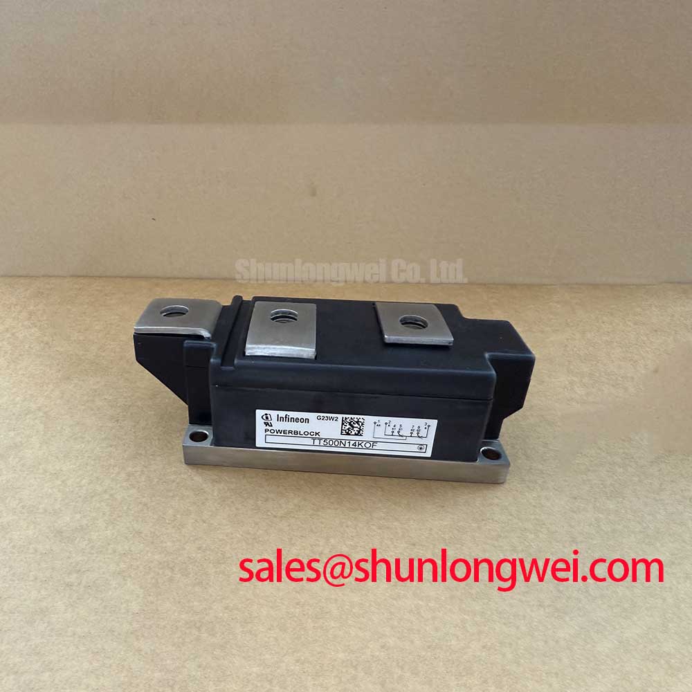
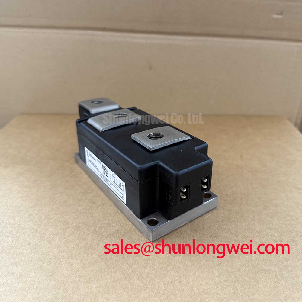
TT500N14KOF Circuit Protection and Reliability for Soft Starter Bypass Control
Before energizing a replacement, isolate the soft starter, inspect the power terminals, and verify the nameplate boundary against the TT500N14KOF ratings. This Infineon dual thyristor module is specified for a 1400 V repetitive peak off-state and reverse voltage, a 500 A mean on-state current at Tc = 85°C, and an 800 A maximum RMS on-state current. The published surge on-state current is 14,500 A for 10 ms at 25°C.
| Parameter | Official Specification |
|---|---|
| Repetitive peak off-state and reverse voltage | VDRM / VRRM: 1400 V |
| Mean on-state current | ITAVM: 500 A at Tc = 85°C |
| Maximum RMS on-state current | ITRMSM: 800 A |
| Surge on-state current | ITSM: 14,500 A for 10 ms at 25°C |
| Critical off-state voltage rise rate | dv/dt: 1000 V/µs |
| Junction-to-case thermal resistance | RthJC: 0.072 K/W |
For a high-voltage three-phase motor solid-state soft starter, phase-angle control should be validated against the motor’s measured starting profile rather than treated as a fixed current-reduction guarantee. The control system, semiconductor fuse, bypass contactor, and thyristor ratings must be coordinated as one protection network. When a higher repetitive voltage class is required by the equipment documentation, engineers may also evaluate the TT500N18KOF as a separate compatibility candidate, subject to terminal layout and electrical verification.
TT500N14KOF Thermal-Electrical Optimization for Surge Protection
The 1000 V/µs dv/dt specification defines an important boundary for commutation and transient evaluation, but it does not replace system-level surge protection. Designers should assess the AC input environment, line impedance, transformer arrangement, switching frequency, and motor cable length before selecting MOVs, RC snubbers, or semiconductor fuses.
For equipment exposed to surge testing or severe industrial switching, the protection network should be evaluated against the applicable system test plan, including the relevant IEC 61000-4-5 setup where applicable. MOV voltage selection must avoid unwanted conduction during normal line operation while limiting transient stress at the thyristor terminals. The RC network should be checked for pulse energy, leakage current, and its effect on commutation. These are Design Considerations, not additional Infineon specifications for this module.
Fuse coordination requires the actual semiconductor fuse I²t clearing value to be compared with the thyristor’s published withstand data. Do not infer a permissible fault duration from the 14,500 A surge figure alone, because that rating is stated for a defined 10 ms condition at 25°C. Terminal wiring should follow the original equipment drawing, with short power paths and controlled routing of gate and auxiliary conductors. The system integrator should verify the required snubber and surge values through measured voltage waveforms.
Assembly Integrity and Heatsink Layout for the TT500N14KOF
The specified RthJC of 0.072 K/W applies from junction to case; it is not the complete thermal path from silicon to ambient air. Heatsink selection must therefore include interface resistance, heatsink temperature, airflow, enclosure conditions, and the duty cycle imposed by the motor starter. A clean, flat mounting surface and an even interface layer help preserve the intended thermal path without distorting the module base.
Mounting hardware should be tightened progressively and according to the Infineon mechanical installation instructions for the applicable package. Since the supplied parameters do not state a mounting torque, the equipment assembler should not substitute a generic torque value. Confirm terminal size, conductor orientation, creepage requirements, and phase identification from the original module drawing before applying power.
During preventive maintenance, inspect the heatsink for dust accumulation, check for signs of thermal-interface drying or displacement, and compare phase terminal temperature under a known operating load. Maintenance Note: Record contact temperature and recheck the cooling airflow after scheduled cleaning or any terminal service. A temperature imbalance may justify further checks of conductor torque, current sharing, gate timing, or heatsink contact rather than immediate replacement of the module.
For background on selection, protection coordination, and power semiconductor reliability practices, consult the Power Electronics Masterclass. The principles are useful for system review, while the TT500N14KOF values above remain the product-specific boundaries.
TT500N14KOF Operational Boundaries and Type-2 Short-Circuit Coordination
Type-2 coordination for a soft starter must be demonstrated with the selected semiconductor fuse, upstream protection, contactor arrangement, and enclosure fault path. The objective is to limit short-circuit energy and prevent unacceptable damage to the thyristor assembly, but the result depends on the fuse clearing characteristic and the prospective fault current at the installation point.
Start by obtaining the fuse manufacturer’s time-current curve and I²t data for the exact fuse family and voltage class. Compare those values with the official TT500N14KOF short-time and surge withstand information, then validate the complete assembly under the equipment maker’s coordination procedure. The 1400 V VDRM/VRRM rating is a blocking-voltage specification; it is not a short-circuit interruption rating.
After a protection event, inspect the module, fuse holders, busbars, gate wiring, and bypass contactor before re-energization. A dead short, abnormal phase current, or repeated fuse operation may involve insulation damage, incorrect gate drive timing, loose terminals, or a downstream motor fault. Oscilloscope measurements and insulation tests should be performed only with procedures appropriate to the voltage class and by qualified personnel. The system engineer must confirm the final fault-clearance margin using the actual installation data.


