





Content last revised on October 29, 2026
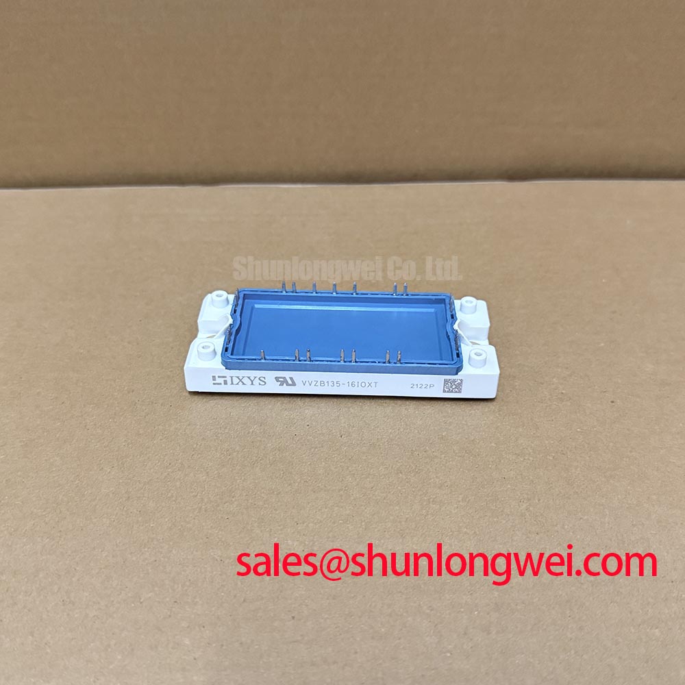
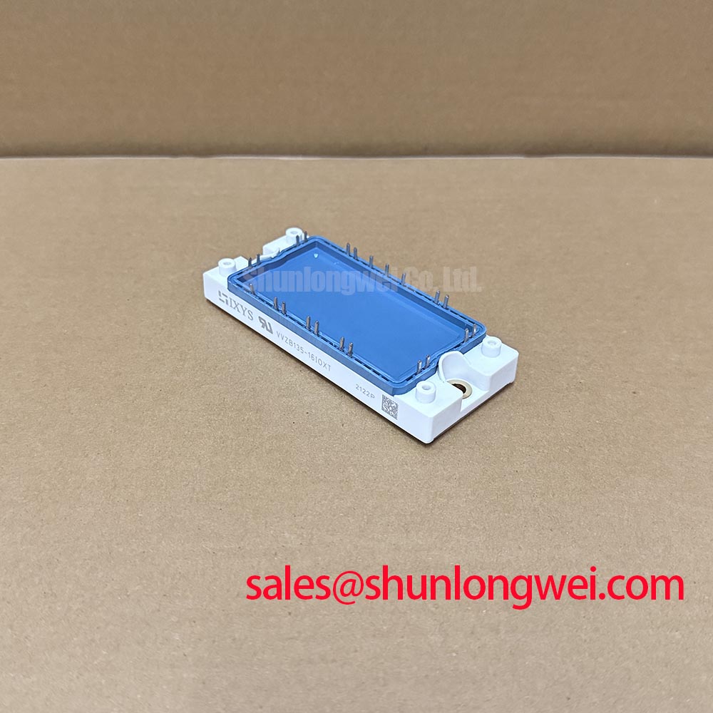
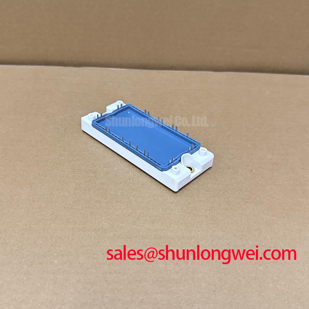
Preventing Spurious Faults: Surge Energy Dissipation and Clamping Volt Guidelines for VVZB135-16IOXT
Trace the incoming surge path through the protective devices, wiring, and bridge connections before changing the MOV network. As a Design Consideration, MOV selection should account for continuous operating voltage, temporary overvoltage, surge current, and residual clamping voltage at the relevant surge waveform. Compare the resulting voltage at the module terminals with its documented blocking limits, including the contribution from connection inductance.
Keep protection connections direct where the equipment layout permits. A clamp mounted remotely can leave appreciable transient voltage across the intervening conductors. Inspect existing MOVs for physical deterioration and assess their condition using the protection-device manufacturer's procedures. A recurring protective trip warrants checking the incoming disturbance and protection network rather than attributing it immediately to the bridge.
For an installed RC snubber, an Engineering Recommendation is to check component condition, resistor pulse capability, and the measured ringing waveform before altering either component. Snubber selection depends on the actual circuit impedance and switching conditions. Equipment surge testing should reference the applicable requirements of IEC 61000-4-5; that standard does not supply a universal MOV or snubber prescription for this module.
Topology also matters when investigating input-current distortion. The Vienna rectifier topology describes an active power-factor-correction architecture. Its controlled switching behavior should not be assigned to VVZB135-16IOXT solely because both involve three-phase rectification. Establish the equipment's actual power circuit before evaluating harmonic-control changes.
VVZB135-16IOXT Thermal-Electrical Optimization: I2t Sub-Cycle Melting Rating Practical Tuning
Compare the fuse's total clearing I²t with the module's documented withstand conditions, rather than selecting protection from fuse current alone. As a Design Consideration, coordination requires the prospective fault current, operating voltage, initial semiconductor temperature, and the time basis of the withstand rating. Fuse pre-arcing I²t describes only part of the clearing event.
Build the coordination record around the installed fuse reference and its manufacturer curves. Include total clearing energy, peak let-through current, breaking capacity, and the semiconductor surge-rating conditions. Check that the fuse data cover the equipment's actual fault duty; an AC clearing characteristic cannot automatically establish performance in a different circuit. This assessment supports protection selection but cannot guarantee damage-free interruption during every short circuit.
Inspect the thermal interface while the module is accessible. Uneven contact, contamination, or a strained mounting arrangement can impair heat transfer and complicate interpretation of overload-related faults. The linked discussion of Mastering IGBT Thermal Management provides broader cooling context; rectifier assembly decisions should follow the applicable module and equipment instructions.
Field Alert: Use the specified terminal and mounting torques, and apply the thermal interface material according to the module and heatsink assembly instructions.
For procurement comparison, include VUO160-16NO7 in a documented electrical and mechanical assessment. Compare circuit configuration, terminal locations, mounting dimensions, thermal requirements, and protection coordination before approving substitution. No drop-in replacement is established by the supplied specifications.
Assembly Integrity & Layout Architecture: Implementing Preventing Localized Gate Hotspot Burnout for VVZB135-16IOXT
Identify which device actually receives firing pulses before investigating gate-related heating. The supplied VVZB135-16IOXT specification establishes a three-phase bridge rectifier but does not establish gate terminals or SCR trigger characteristics. Assigning gate-current, gate-voltage, or pulse-rise-time requirements to this model would therefore exceed its confirmed product definition.
Where the surrounding equipment contains a separately identified thyristor stage, treat its trigger circuit as a separate diagnostic task. As a Design Consideration, compare pulse amplitude, duration, polarity, and repetition against that thyristor's specifications under the intended load conditions. The distinction between triggering, latching, and holding behavior is explained in the reference on thyristor and SCR operation. Phase-angle adjustments also change current waveforms, so harmonic assessment belongs to the complete controlled stage.
When evaluating a grid-tied static var compensator or thyristor-switched capacitor assembly, verify the rectifier's assigned subsystem rather than treating it as the capacitor-switching element. An Engineering Recommendation is to compare the power schematic, auxiliary supply paths, and terminal schedule during compatibility review. The VUB71-16NO1 can be considered in that wider topology review, with its own circuit configuration and interface requirements checked independently.