
Content last revised on September 10, 2026
Turn-On Current Rise Limiting (di/dt): Preventing Localized Cathode Finger Burnout
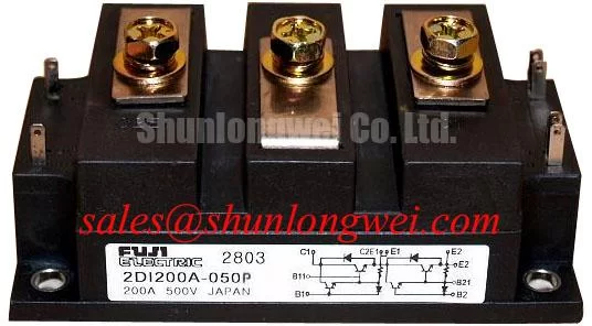
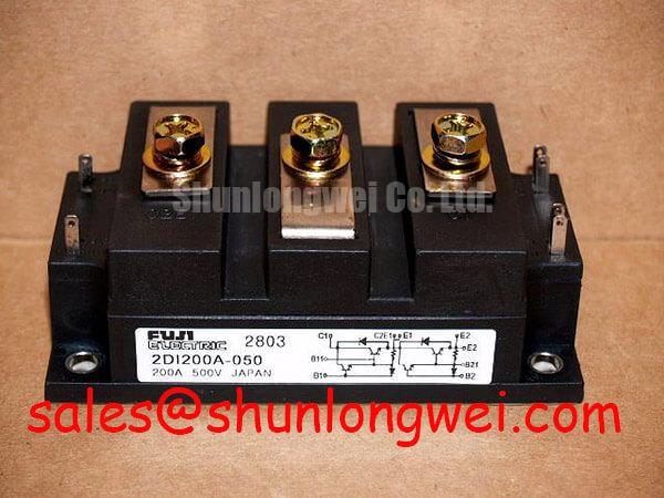
In high-current green hydrogen electrolyzer DC power rectifiers, rapid dynamic load shifts and pulsed operating regimes subject power modules to substantial turn-on current gradients. The Fuji Electric 2DI200A-050 provides a continuous collector/forward current rating of 200A and a maximum voltage rating of 500V. During high di/dt switching transitions, conduction initiates in localized regions adjacent to the gate and base contact metallization before spreading across the entire active silicon junction area. If the critical rate of current rise is exceeded, current filamentation causes severe localized heating, increasing the risk of thermal runaway and junction degradation.
To mitigate high di/dt stress, primary DC rectifier stages implement snubber circuits and series inductances to limit current slope:
- Snubber Design: RC snubber networks placed across the module clamp transient overvoltages and constrain the turn-off dv/dt to safe operating levels below critical thresholds.
- Series Inductive Limiting: Saturable reactors or localized busbar inductances maintain low initial current gradients during conduction spread, ensuring full junction activation before peak current conduction.
- Thermal Dissipation Integrity: The junction-to-case thermal resistance Rth(j-c) requires optimized thermal interface material (TIM) coverage. Baseplate mounting torque must adhere strictly to 3.5–4.5 N·m to prevent package deformation while maintaining uniform thermal contact.
For auxiliary rectifier rails or lower-current bias stages within the same power architecture, the 2DI75D-055A serves as a complementary topology device for scaled current paths.
Evaluating Post-Surge Reverse Voltage Blocking Recovery at Elevated Junction Temperatures
Electrolyzer rectifiers are frequently exposed to line disturbances, sudden cell load steps, and AC grid fluctuations that induce high surge current events. The 2DI200A-050 module possesses an integrated non-repetitive surge rating (ITSM) and a maximum operating junction temperature Tj of up to +150°C. Following a 10 ms sinusoidal half-cycle surge, the energy dissipated internally elevates the junction temperature significantly above steady-state equilibrium.
The device's capacity to restore reverse voltage blocking (up to VRRM / VCEO = 500V) depends directly on the remaining thermal headroom. High post-surge junction temperatures accelerate leakage current generation, which can initiate thermal runaway if the reverse voltage is reapplied before adequate cooling occurs:
| Parameter | Specification / Rating | Operational Implication in Electrolyzer Rectifiers |
|---|---|---|
| Collector-Emitter Voltage (VCEO) | 500V | Defines peak continuous DC bus reverse blocking headroom. |
| Continuous Collector Current (IC) | 200A | Direct rated baseline for continuous electrolysis cell current. |
| Max Junction Temperature (Tj) | +150°C | Thermal ceiling determining safe I2t fuse and breaker clearing margins. |
When DC link bus architectures demand elevated voltage margins for series-stacked electrolytic cells, the related 2DI200-100 provides an increased 1000V blocking rating under identical package dimensions.
Diode Peak Reverse Recovery Current (I_rrm) and Softness Factor Characteristics
The integrated free-wheeling diode inside the 2DI200A-050 carries up to 200A of forward current (IF) and undergoes rapid commutation during cyclic power transfer in switch-mode electrolyzer supplies. The reverse recovery process involves the evacuation of stored minority carriers, characterized by the reverse recovery time (trr), peak reverse recovery current (Irrm), and reverse recovery charge (Qrr).
The reverse recovery current waveform is split into two phases: the current fall phase (ta) and the subsequent recovery phase (tb). The softness factor (S = tb / ta) determines the rate of diR/dt during turn-off:
- Snap-Off Suppression: A soft recovery characteristic (high S-factor) prevents abrupt current cessation, limiting induced transient voltages (Vpeak = Lσ · diR/dt) generated across parasitic busbar inductances (Lσ).
- Electromagnetic Interference (EMI): Controlled diode commutation damping reduces high-frequency RF emission in the rectifier enclosure.
- Commutation Power Losses: The product of instantaneous reverse voltage and reverse recovery current contributes to dynamic switching losses, requiring calculated heatsink sizing according to the Fuji Electric Power Semiconductors Portal thermal guidelines.
High-di/dt Gate Firing: Pulse-Train Timing and Critical Latching Current Dynamics
Operating high-current power switching modules in electrochemical rectification systems requires strict adherence to gate/base drive dynamics. The internal Darlington configuration relies on proper drive current amplitude and steep rise times (diG/dt > 1 A/μs) to force the output section into deep saturation rapidly.
Key gate and base driving criteria include:
- Pulse-Train and Back-Porch Current: A strong initial trigger pulse ensures complete silicon channel ignition, followed by a sustained continuous porch current that prevents the device from dropping out of saturation under fluctuating electrolyzer load conditions.
- Latching and Holding Current Thresholds: Maintaining forward drive above the module's critical latching current ensures uniform current density across all paralleled internal emitter/collector fingers, mitigating localized hotspots.
- Reliability Verification: For diagnostic verification, gate drive isolation checks, and dynamic waveform inspection protocols, refer to the testing methodologies published in the Field Engineer’s Handbook.
Careful coordination of drive signals, thermal dissipation networks, and snubber protection ensures deterministic electrical performance of the 2DI200A-050 module across the lifetime of industrial hydrogen generation plants.